Figure 6. write-0 time slot, Figure 7. write-1 and read-data time slot, Wire write byte – Rainbow Electronics DS2482-800 User Manual
Page 13
DS2482-800: Eight-Channel 1-Wire Master
13 of 22
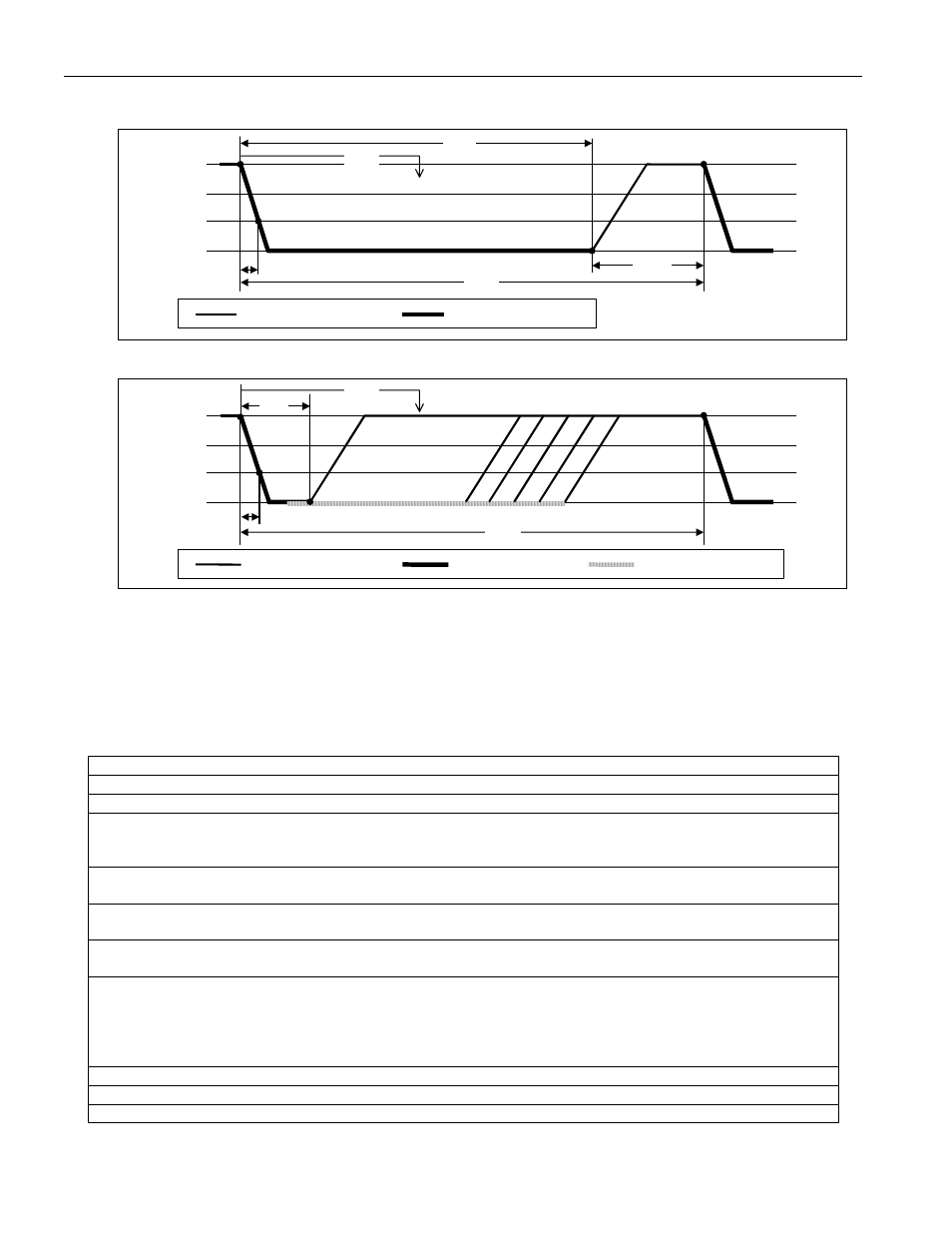
Figure 6. Write-0 Time Slot
Pullup (see Fig. 2)
DS2482 Pulldown
t
REC0
V
cc
V
IH1
V
IL1
0V
t
F1
t
SLOT
t
W0L
t
MSR
Figure 7. Write-1 and Read-Data Time Slot
Pullup (see Fig. 2)
DS2482 Pulldown
1-W Slave Pulldown
V
cc
V
IH1
V
IL1
0V
t
F1
t
SLOT
t
W1L
t
MSR
NOTE on Figure 7: Depending on its internal state, a 1-Wire slave device will transmit data to its master (e.g., the
DS2482). When responding with a 0, a 1-Wire slave will start pulling the line low during t
W1L
; its internal timing
generator determines when this pulldown ends and the voltage starts rising again. When responding with a 1, a 1-
Wire slave will not hold the line low at all, and the voltage starts rising as soon as t
W1L
is over. 1-Wire device data
sheets use the term t
RL
instead of t
W1L
to describe a read-data time slot. Technically, t
RL
and t
W1L
have identical
specifications and cannot be distinguished from each other.
1-Wire Write Byte
Command Code
A5h
Command Parameter
Data Byte
Description
Writes single data byte to selected 1-Wire IO channel.
Typical Use
To write commands or data to a 1-Wire IO channel; equivalent to
executing eight 1-Wire Single Bit commands, but faster due to less I²C
traffic.
Restriction
1-Wire activity must have ended before the DS2482 can process this
command.
Error Response
Command code and data byte will not be acknowledged if 1WB = 1 at the
time the command code is received and the command will be ignored.
Command Duration
8 × t
SLOT
+ maximum 262.5ns, counted from falling edge of the last bit (LS
bit) of the data byte.
1-Wire Activity
Begins maximum 262.5ns after falling SCL edge of the LS bit of the data
byte (i.e., before the data byte acknowledge).
NOTE: The bit order on the I²C bus and the 1-Wire line is different.
(1-Wire: LS-bit first; I²C: MS-bit first) Therefore, 1-Wire activity cannot
begin before the DS2482 has received the full data byte.
Read Pointer Position
Status Register (for busy polling)
Status Bits Affected
1WB (set to 1 for 8 × t
SLOT
)
Configuration Bits Affected 1WS, SPU, APU apply