Electrical characteristics, Absolute maximum ratings – Rainbow Electronics DS2482-800 User Manual
Page 2
DS2482-800: Eight-Channel 1-Wire Master
2 of 22
ABSOLUTE MAXIMUM RATINGS
Voltage Range on Any Pin Relative to Ground
-0.5V, +6V
Maximum Current Into Any Pin
±20mA
Operating Temperature Range
-40°C to +85°C
Junction Temperature
+150°C
Storage Temperature Range
-55°C to +125°C
Soldering Temperature
See IPC/JEDEC J-STD-020A
Stresses beyond those listed under “Absolute Maximum Ratings” may cause permanent damage to the device. These are stress ratings only,
and functional operation of the device at these or any other conditions beyond those indicated in the operational sections of the specifications is
not implied. Exposure to the absolute maximum rating conditions for extended periods may affect device.
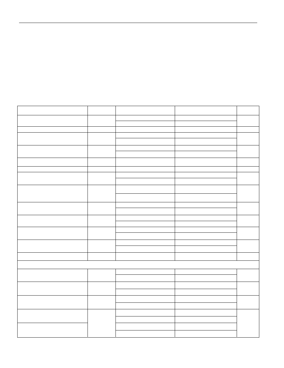
ELECTRICAL CHARACTERISTICS
(V
CC
= 2.9V to 5.5V, T
A
= -40°C to +85°C.)
PARAMETER SYMBOL
CONDITIONS
MIN
TYP
MAX
UNITS
3.3V 2.9
3.3
3.7
Supply Voltage
V
CC
5V 4.5
5.0
5.5
V
Operating Current
I
CC
(Note
1)
0.75 mA
3.3V (Notes 2, 3)
1.9
1-Wire Input High
V
IH1
5V (Notes 2, 3)
3.4
V
3.3V (Notes 2, 3)
0.75
1-Wire Input Low
V
IL1
5V (Notes 2, 3)
1.0
V
1-Wire Weak Pullup Resistor
R
WPU
(Note
4)
800 1675 W
1-Wire Output Low
V
OL1
At 4mA load
0.4
V
Standard (Notes 4, 5)
2.3
2.5
2.7
Active Pullup On Time
t
APUOT
Overdrive (Notes 4, 5)
0.4
0.5
0.6
µs
V
CC
³ 3.2V, 1.5mA load
0.3
Strong Pullup Voltage Drop
DV
STRPU
V
CC
³ 5.2V, 3mA load
0.5
V
Standard (3.3V
±5%)
1 4.2
3.3V Pulldown Slew Rate
(Note 6)
PD
SRC
Overdrive (3.3V
±5%)
5 22.1
V/µs
Standard (5.0V
±5%)
2 6.5
5V Pulldown Slew Rate
(Note 6)
PD
SRC
Overdrive (5.0V
±5%)
10 40
V/µs
Standard (3.3V
±5%)
0.8 4
3.3V Pullup Slew Rate (Note 6)
PU
SRC
Overdrive (3.3V
±5%)
1.3 6
V/µs
Standard (5.0V
±5%)
2.7 20
5V Pullup Slew Rate (Note 6)
PU
SRC
Overdrive (5.0V
±5%)
3.4 31
V/µs
Power-On Reset Trip Point
V
POR
2.2
V
1-Wire TIMING (Note 16) See Figures 3, 5, 6, and 7
Standard
7.6
8
8.4
Write 1/Read Low Time
t
W1L
Overdrive 0.9
1
1.1
µs
Standard 13.3
14
15
Read Sample Time
t
MSR
Overdrive 1.4
1.5
1.8
µs
Standard 65.8
69.3
72.8
1-Wire Time Slot
t
slot
Overdrive 9.9
10.5
11.0
µs
3.3V to 0V (Note 5)
0.6
2.6
Fall Time High-to-Low at
Standard Speed (Note 6)
5.5V to 0V (Note 5)
0.7
2.2
3.3V to 0V (Note 5)
0.1
0.5
Fall Time High-to-Low at
Overdrive Speed (Note 6)
t
F1
5.5V to 0V (Note 5)
0.1
0.4
µs