Rainbow Electronics DS2482-800 User Manual
Page 16
DS2482-800: Eight-Channel 1-Wire Master
16 of 22
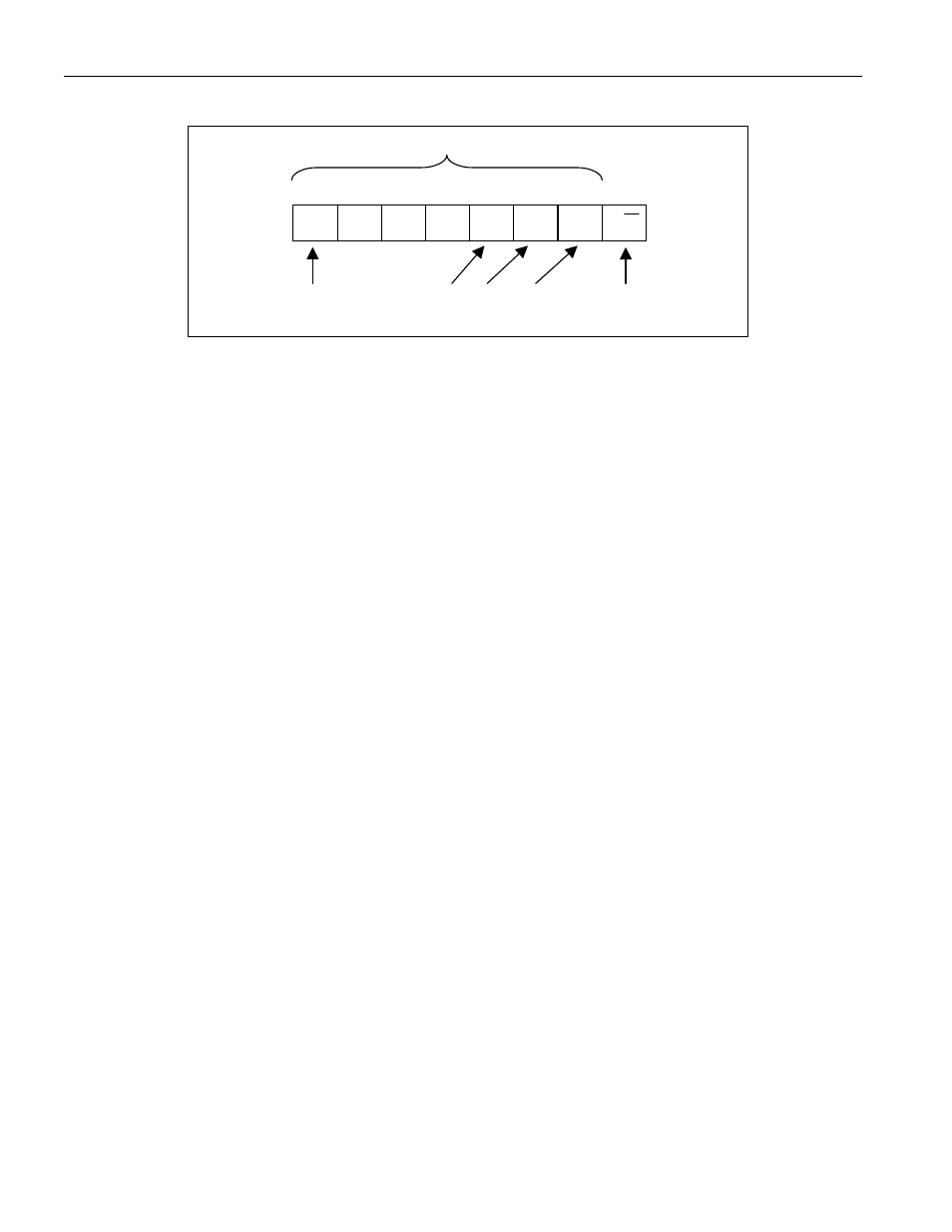
Figure 9. DS2482 Slave Address
A6
A5
A4
A3
A2
A1
A0
0
1
1
0
AD2 AD1 AD0 R/W
7-Bit Slave Address
Most Signi-
ficant Bit
Determines
Read or Write
AD2, AD1, AD0
Pin States
I²C Definitions
The following terminology is commonly used to describe I²C data transfers. The timing references are defined in
Figure 10.
Bus Idle or Not Busy: Both, SDA and SCL, are inactive and in their logic HIGH states.
START Condition: To initiate communication with a slave, the master has to generate a START condition. A
START condition is defined as a change in state of SDA from HIGH to LOW while SCL remains HIGH.
STOP Condition: To end communication with a slave, the master has to generate a STOP condition. A STOP
condition is defined as a change in state of SDA from LOW to HIGH while SCL remains HIGH.
Repeated START Condition: Repeated starts are commonly used for read accesses to select a specific data
source or address to read from. The master can use a repeated START condition at the end of a data transfer to
immediately initiate a new data transfer following the current one. A repeated START condition is generated the
same way as a normal START condition, but without leaving the bus idle after a STOP condition.
Data Valid: With the exception of the START and STOP condition, transitions of SDA may occur only during the
LOW state of SCL. The data on SDA must remain valid and unchanged during the entire high pulse of SCL plus
the required setup and hold time (t
HD:DAT
after the falling edge of SCL and t
SU:DAT
before the rising edge of SCL, see
Figure 10). There is one clock pulse per bit of data. Data is shifted into the receiving device during the rising edge
of the SCL.
When finished with writing, the master must release the SDA line for a sufficient amount of setup time (minimum
t
SU:DAT
+ t
R
in Figure 10) before the next rising edge of SCL to start reading. The slave shifts out each data bit on
SDA at the falling edge of the previous SCL pulse and the data bit is valid at the rising edge of the current SCL
pulse. The master generates all SCL clock pulses, including those needed to read from a slave.
Acknowledge: Usually, a receiving device, when addressed, is obliged to generate an acknowledge after the
receipt of each byte. The master must generate a clock pulse that is associated with this acknowledge bit. A device
that acknowledges must pull SDA LOW during the acknowledge clock pulse in such a way that SDA is stable LOW
during the HIGH period of the acknowledge-related clock pulse plus the required setup and hold time (t
HD:DAT
after
the falling edge of SCL and t
SU:DAT
before the rising edge of SCL).
Not Acknowledged by Slave: A slave device may be unable to receive or transmit data, e.g., because it is busy
performing some real-time function. In this case the slave device will not acknowledge its slave address and leave
the SDA line HIGH.
A slave device that is ready to communicate will acknowledge at least its slave address. However, some time later
the slave may refuse to accept data, e.g., because of an invalid command code or parameter. In this case the slave
device will not acknowledge any of the bytes that it refuses and will leave SDA HIGH. In either case, after a slave
has failed to acknowledge, the master first needs to generate a repeated START condition or a STOP condition
followed by a START condition to begin a new data transfer.