Table 20. mfr_mode_output bit definition – Rainbow Electronics MAX16064 User Manual
Page 47
MAX16064
±0.3% Accurate, Quad, Power-Supply Controller with
Active-Voltage Output Control and PMBus Interface
______________________________________________________________________________________
47
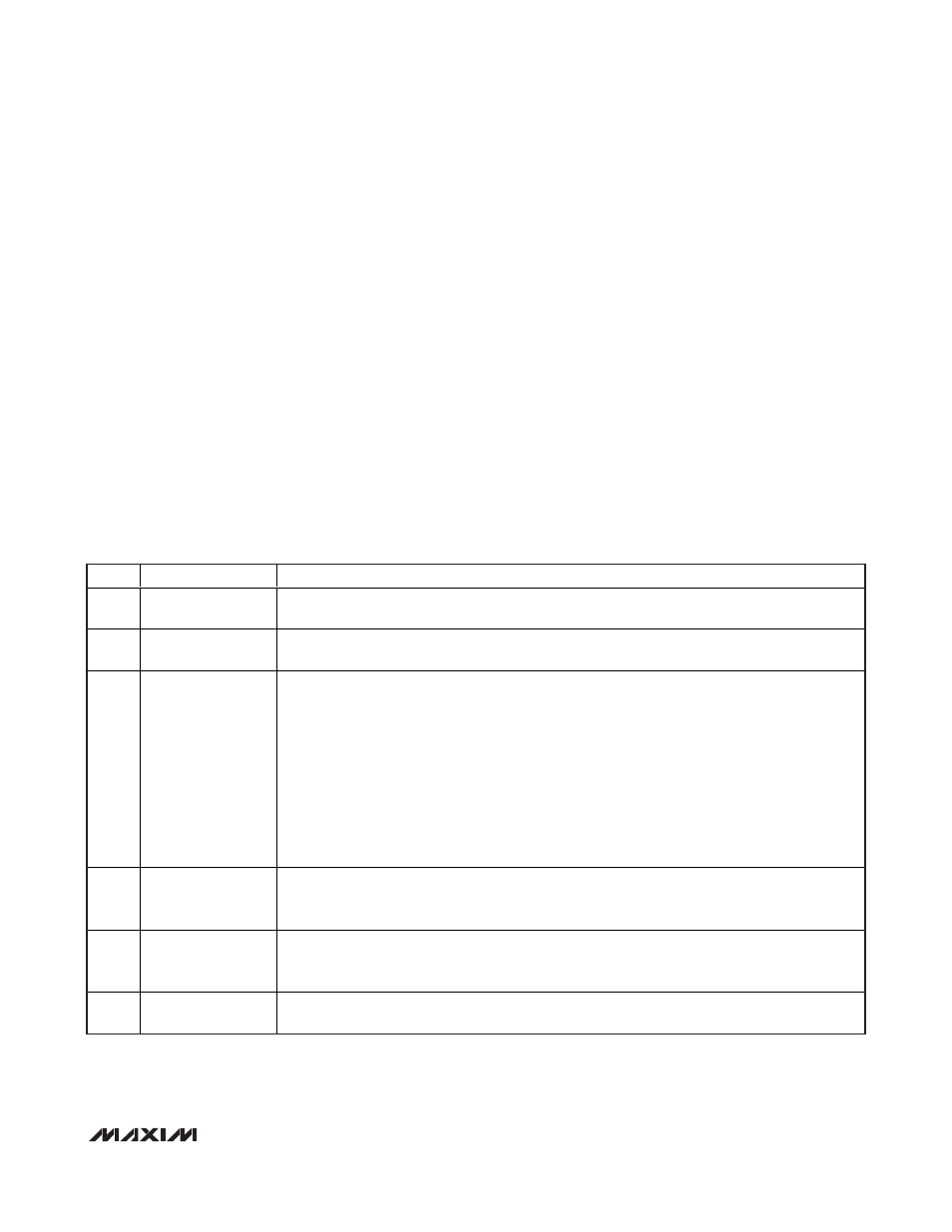
Table 20. MFR_MODE_OUTPUT Bit Definition
BIT
BIT NAME
DESCRIPTION
5
DAC Switch Mode
1 = DAC switch is open when REFIN mode power supply is turned off.
0 = DAC switch remains closed when REFIN mode power supply is turned off.
4
Global Fault Select
1 = Faults on this output causes faults on other outputs as well.
0 = Faults on this output only affects this output (default).
3
Input Range Select
The Input Range Select bit determined the full-scale range of the RS+/RS- voltage conversion.
1 = 5.5V.
0 = 2.0V (default).
Prior to sending any voltage-related commands, the user application must first configure the
desired input range. All voltage-related commands use the specified input range to convert the
commanded value to internal register values.
Changing the Input Range Select bit while the power supply is on is not recommended. This may
result in unpredictable and possible catastrophic operation since all voltage-related commands
continue to refer to the input range that was in effect when the command was received.
2
ENOUT Polarity
Select
The ENOUT Polarity bit selects the ENOUT active-on polarity. See the ENOUT_ Operation section.
1 = ENOUT asserted on-state is the same as the default startup state (low).
0 = ENOUT asserted on-state is the inverse of the default startup state (high).
1
Feedback Mode
Select
The Feedback Mode Select bit selects the closed-loop voltage control operation mode.
1 = Feedback mode.
0 = Refin mode (default).
0
Page 255 Control
1 = Writes when PAGE = 255 does not affect this output.
0 = Writes when PAGE = 255 affects this output (default).
MFR_SET_ADDRESS (DBh)
The MFR_SET_ADDRESS command is used to change
the MAX16064 slave address. By default the
MAX16064 address is set by A3:A1 upon reset accord-
ing to Table 3. After reset, the slave address can be
changed by the MFR_SET_ADDRESS command. See
the
MAX16064 Address Assignment
section.
This command has 2 data bytes. The slave address is
contained in bits [6:0] of the first data byte. Bit 7 of the
first data byte must be 0.
MFR_RESET_DELAY (DDh)
MFR_RESET_DELAY sets the reset timeout, t
RP
, from
when the associated power-supply output voltage
reaches regulation and the RESET output deasserts
(see Figure 9). The reset timeout is also dependent
upon MFR_SAMPLE_RATE. The minimum t
RP
is calcu-
lated as follows:
t
RP
= (MFR_RESET_DELAY) x [MFR_SAMPLE_RATE x
(100 x 10
-6
)]
For example, if MFR_RESET_DELAY = 20 and
MFR_SAMPLE_RATE = 50, then the minimum reset
timeout period is t
RP
= (20) x [50 x (100 x 10
-6
)
] =
100ms.
Note that the resolution of t
RP
is MFR_SAMPLE_RATE x
100µs, so in this example is 50 x 100µs = 5ms.
The 2 data bytes are in DIRECT format. Valid values are
from 0 to 3276.7ms.
The default MFR_RESET_DELAY value is 0ms.
MFR_MODE_OUTPUT (DEh)
The MFR_MODE_OUTPUT command is described in
Table 20.