Table 1a. conversion rules, Table 1b. 16-bit words stored in eeprom – Rainbow Electronics MAX16064 User Manual
Page 17
MAX16064
±0.3% Accurate, Quad, Power-Supply Controller with
Active-Voltage Output Control and PMBus Interface
______________________________________________________________________________________
17
Finally, the AVOC system uses a separate control loop
rate that is related to the total ADC conversion rate. The
value of register MFR_DAC_ACT_CNT sets the number
of total ADC conversion cycles (one cycle is a complete
set of ADC conversions for 4 voltages and 1 tempera-
ture) that must occur before AVOC changes the DAC
output voltage. Smaller values of MFR_DAC_ACT_CNT
shorten the adjustment time. Larger values of
MFR_DAC_ACT_CNT adjust the output voltage at much
slower rates, reducing possible negative effects on the
power-supply control loop.
External EEPROM Interface
The MAX16064 can communicate with an EEPROM
attached to the A1/SCLE and A2/SDAE. The MAX16064
communicates to the EEPROM with an address byte of
1010 0000 for writing and 1010 0001 for reading. For
the data values of 2 bytes, the most significant byte is
stored in the lower address of the EEPROM, whereas
the least significant byte is stored in the higher address
of the EEPROM.
Upon reset, the MAX16064 tests for the presence of a
configuration EEPROM. It searches for the SIGNATURE
bytes in the attached EEPROM. If the SIGNATURE
bytes are present, it concludes that it has a valid con-
figuration EEPROM and starts reading configuration
information from the attached EEPROM. If the slave
address (MFR_SET_ADDRESS) is a value other than
0x00, this overrides the slave address information pre-
viously set by the address A3:A1 pins.
Table 1b shows the contents and addresses of the con-
figuration information expected by the MAX16064. This
information is for reference only. It is recommended to
use a properly configured, working MAX16064 to save
its state to the EEPROM and limit direct modifications to
as few fields as possible (such as the slave address).
Temperature and voltage values are stored in an inter-
nal representation, which is not the same as the format
used by the corresponding PMBus commands. For
details on the EEPROM internal representation, see
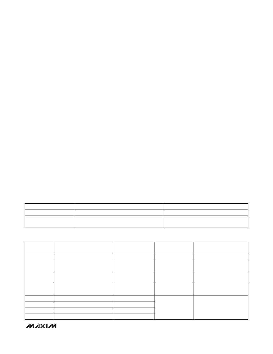
Conversion Rules (Table 1a).
For example, to store to the EEPROM PAGE 2
VOUT_COMMAND = 3.0V, m = 19995, b = 0, R = -1.
First calculate the PMBUS command value, which is
5998. If the voltage range is 2V, no conversion is
required. Hence write 17h to address 28 and 6Eh to
address 29. If the voltage range is 5.5V, the stored
EEPROM value = 5998/2.75 = 2181. So write 08h to
address 28 and write 85h to address 29.
Note that the conversion is automatically handled by
the MAX16064 when it stores and loads configuration
information.
Table 1a. Conversion Rules
READ (INTERNAL TO PMBus)
WRITE (PMBus TO INTERNAL)
TEMPERATURE
Subtract 3010 (decimal) from the PMBus value
Add 3010 (decimal) to the PMBus value
VOLTAGE
No conversion in 2V mode;
multiply by 2.75 in 5.5V mode
No conversion in 2V mode;
divide by 2.75 in 5.5V mode
Table 1b. 16-Bit Words Stored in EEPROM
EEPROM
ADDRESS
NAME
PAGE
PMBus COMMAND
NOTES
0
MFR_FAULT_REASON
—
0E2h
—
2
MFR_MODE
—
0D1h
Must also match
MFR_TICK_RELOAD
4
TEMPERATURE_PEAK
—
0D6h
Internal representation
(temperature)
6
MFR_FAULT_TEMP
—
0E4h
Internal representation
(temperature)
8
MFR_VOUT_PEAK
0
10
MFR_VOUT_PEAK
1
12
MFR_VOUT_PEAK
2
14
MFR_VOUT_PEAK
3
0D4h
Internal representation
(voltage)