Temperature sensing – Rainbow Electronics MAX16064 User Manual
Page 16
MAX16064
±0.3% Accurate, Quad, Power-Supply Controller with
Active-Voltage Output Control and PMBus Interface
16
______________________________________________________________________________________
Temperature Sensing
To obtain useful temperature readings, place the
MAX16064 in close proximity to the power supplies.
The on-chip temperature sensor on the MAX16064
senses the temperature of the die, which is related to
the exposed pad temperature of the MAX16064 by the
junction-to-case thermal resistance. The exposed pad
of the MAX16064 can connect to the heat dissipating
ground plane of the power supplies, and the power
supplies’ boards can be characterized to obtain the
relationship between the power supplies’ temperature
and temperature as measured by the MAX16064. This
information can be used to set overtemperature fault
settings in the MAX16064.
ADC Conversion, Monitoring,
and AVOC Adjustment Rates
Several timing parameters control the rate at which the
MAX16064 monitors voltages and temperatures and the
rate at which the MAX16064 adjusts the power-supply
output voltages. Each of the four voltage input channels
and the single temperature channel conversions are
performed round-robin fashion. If the input filter is
turned on by setting register MFR_MODE[1] to 0, then
four conversions are performed for each channel
instead of just one. A small programmable delay is
inserted in between each conversion, determined by
the MFR_VLTO register. This establishes the total con-
version rate of the voltages and temperature. Smaller
values of MFR_VLTO results in a higher sampling rate,
and larger values of MFR_VLTO allow for more ADC
settling time.
The ADC conversion result registers are compared to
the fault threshold registers at a rate that is indepen-
dent of the total conversion rate. The value of register
MFR_SAMPLE_RATE determines how frequently this
comparison occurs. Using higher fault comparison
rates increases glitch sensitivity, but slows the
response time of the MAX16064 to PMBus commands.
Using lower fault comparison rates makes the
MAX16064 less sensitive to power-supply output volt-
age glitches.
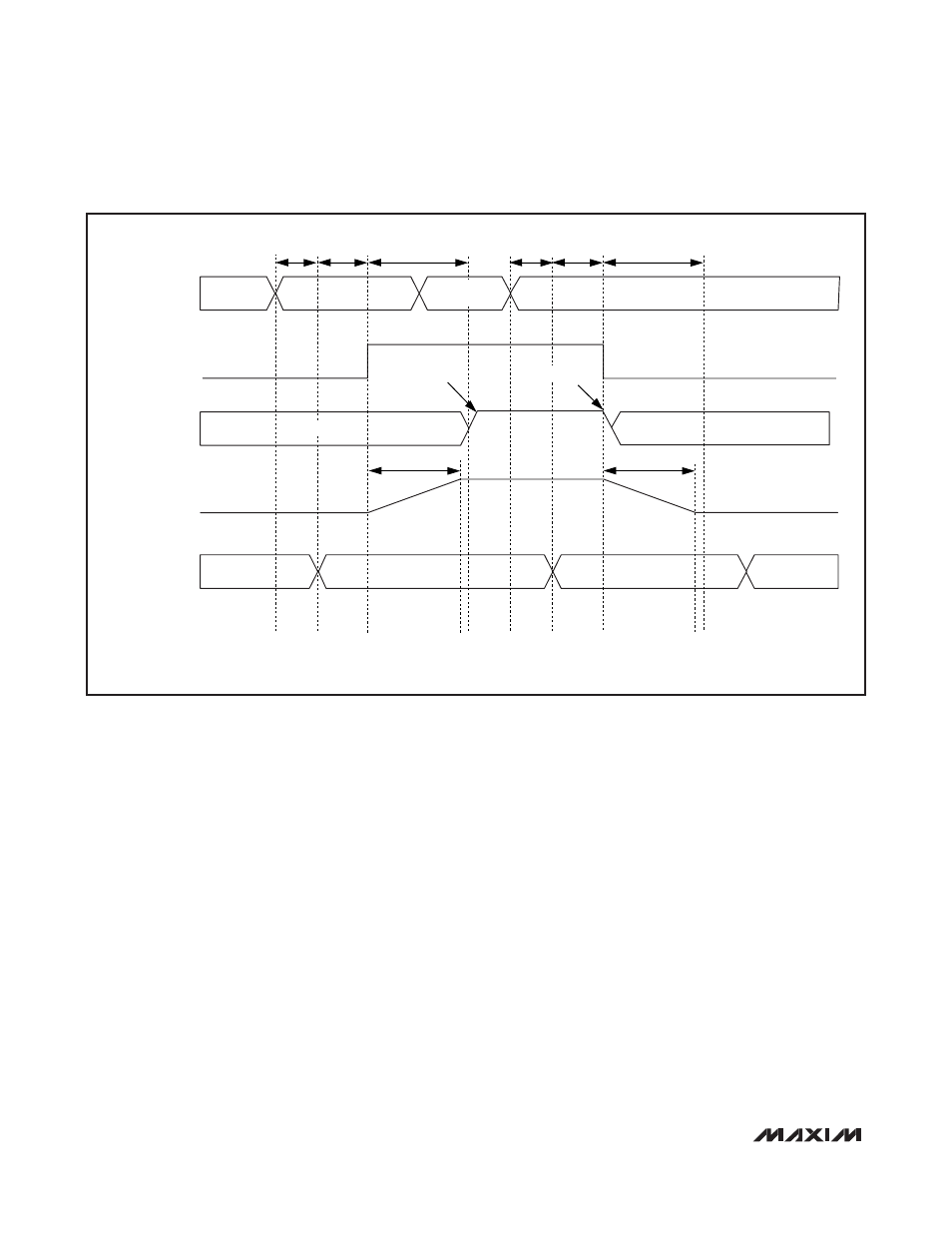
PMBus
OPERATION
ON
IDLE
IDLE
t
PMB_RSP
t
ON_DELAY
t
ON_RISE
t
PS_RISE
t
PS_FALL
t
PMB_RSP
t
OFF_DELAY
t
OFF_FALL
HIGH-Z
ENOUT_
DAC OUTPUT
POWER-SUPPLY
V
OUT
POWER-SUPPLY
OPERATION
IN FB MODE, t
PS_RISE
AND t
PS_FALL
ARE NOT CONTROLLED BY THE MAX16064 AND ARE DEPENDENT ON POWER-SUPPLY IMPLEMENTATION.
CLOSE S_
TURN-ON
TURN-OFF
OPEN S_
HIGH-Z
OPERATION
OFF
Figure 6. Feedback Mode Timing