Pin description, Bit microcontroller with infrared module maxq613, Pin configurations (continued) pin description – Rainbow Electronics MAXQ613 User Manual
Page 9
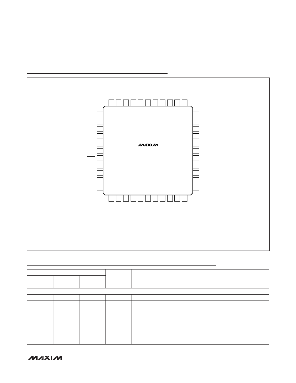
16-Bit Microcontroller with Infrared Module
MAXQ613
_______________________________________________________________________________________ 9
Pin Configurations (continued)
Pin Description
TQFP
(10mm × 10mm)
TOP VIEW
12 P1.1/INT1
13 P1.2/INT2
14 P1.3/INT3
15 N.C.
16 N.C.
17 GND
18 REGOUT
19 V
DD
20 GND
21 P1.4/INT4
22 P1.5/INT5
P2.3/SSEL
33
HFXOUT
24
HFXIN
23
P1.6/INT6
25
P1.7/INT7
26
P2.0/MOSI
27
GND
28
P2.1/MISO
29
N.C.
30
N.C.
31
P2.2/SCLK
32
P0.0/IRTXM/INT8
1
N.C.
2
P0.1/RX/INT9
3
N.C.
4
P0.2/TX/INT10
5
P0.3/INT11
6
P0.4/INT12
7
P0.5/TBA0/TBA1/INT13
8
P0.6/TBB0/INT14
9
P1.0/INT0
11
P0.7/TBB1/INT15
10
34
P2.4/TCK
44
IRRX
43
IRTX
NOTE: CONTACT FACTORY FOR BARE DIE PAD CONFIGURATION.
42
GND
41
V
DD
40
RESET
39
P2.7/TDO
38
P2.6/TMS
37
N.C.
36
N.C.
35
P2.5/TDI
MAXQ613
+
PIN
NAME
FUNCTION
BARE DIE
32 TQFN-
EP/LQFP
44 TQFN-
EP/TQFP
POWER PINS
15, 36
15, 29
19, 41
V
DD
Supply Voltage
13, 16, 25,
37
13, 22, 30
17, 20, 28,
42
GND
Ground. Connect directly to the ground plane.
14
14
18
REGOUT
1.8V Regulator Output. This pin must be connected to ground through
a 1.0FF (ESR: 2
W–10W) external ceramic-chip capacitor. The capacitor
must be placed as close to this pin as possible. No devices other than
the capacitor should be connected to this pin.
—
—
—
EP
Exposed Pad (TQFN Only). Connect EP directly to the ground plane.