In-circuit debug and jtag interface, Operating modes, Figure 10. in-circuit debugger – Rainbow Electronics MAXQ613 User Manual
Page 22: Bit microcontroller with infrared module maxq613
16-Bit Microcontroller with Infrared Module
MAXQ613
22 _____________________________________________________________________________________
To erase, the following function would be used:
/* Erase the given Flash page
* addr: Flash offset (anywhere within page)
*/
int flash_erasepage(uint16_t addr);
The in-application flash memory programming must call
ROM utility functions to erase and program any of the
flash memory. Memory protection is enforced by the
ROM utility functions. In-application is not available in
ROM-only versions of the device.
In-Circuit Debug and JTAG
Interface
Embedded debug hardware and software are devel-
oped and integrated to provide full in-circuit debugging
capability in a user-application environment. These hard-
ware and software features include the following:
• Debug engine
• Set of registers providing the ability to set breakpoints
on register, code, or data using debug service rou-
tines stored in ROM
Collectively, these hardware and software features sup-
port two modes of in-circuit debug functionality:
• Background mode:
CPU is executing the normal user program
Allows the host to configure and set up the in-circuit
debugger
• Debug mode:
Debugger takes over the control of the CPU
Read/write accesses to internal registers and memory
Single-step of the CPU for trace operation
The interface to the debug engine is the TAP control-
ler. The interface allows for communication with a bus
master that can either be automatic test equipment or a
component that interfaces to a higher level test bus as
part of a complete system. The communication operates
across a 4-wire serial interface from a dedicated TAP
that is compatible with the JTAG IEEE Standard 1149.
The TAP provides an independent serial channel to com-
municate synchronously with the host system.
To prevent unauthorized access of the protected memo-
ry regions through the JTAG interface, the debug engine
prevents modification of the privilege registers and
disallows all access to system memory, unless memory
protection is disabled. In addition, all services (such as
register display or modification) are denied when code
is executing inside the system area. The debugger is not
available for ROM-only versions of the device.
Operating Modes
The lowest power mode of operation is stop mode. In this
mode, CPU state and memories are preserved, but the
CPU is not actively running. Wake-up sources include
external I/O interrupts, the power-fail warning interrupt,
wake-up timer, or a power-fail reset. Any time the micro-
controller is in a state where code does not need to be
executed, the user software can put the device into stop
mode. The nanopower ring oscillator is an internal ultra-
low-power (400nA) 8kHz ring oscillator that can be used
to drive a wake-up timer that exits stop mode. The wake-
up timer is programmable by software in steps of 125Fs
up to approximately 8s.
The power-fail monitor is always on during normal opera-
tion. However, it can be selectively disabled during stop
mode to minimize power consumption. This feature is
enabled using the power-fail monitor disable (PFD) bit
in the PWCN register. The reset default state for the PFD
bit is 1, which disables the power-fail monitor function
during stop mode. If power-fail monitoring is disabled
(PFD = 1) during stop mode, the circuitry responsible
for generating a power-fail warning or reset is shut down
and neither condition is detected. Thus, the V
DD
< V
RST
condition does not invoke a reset state.
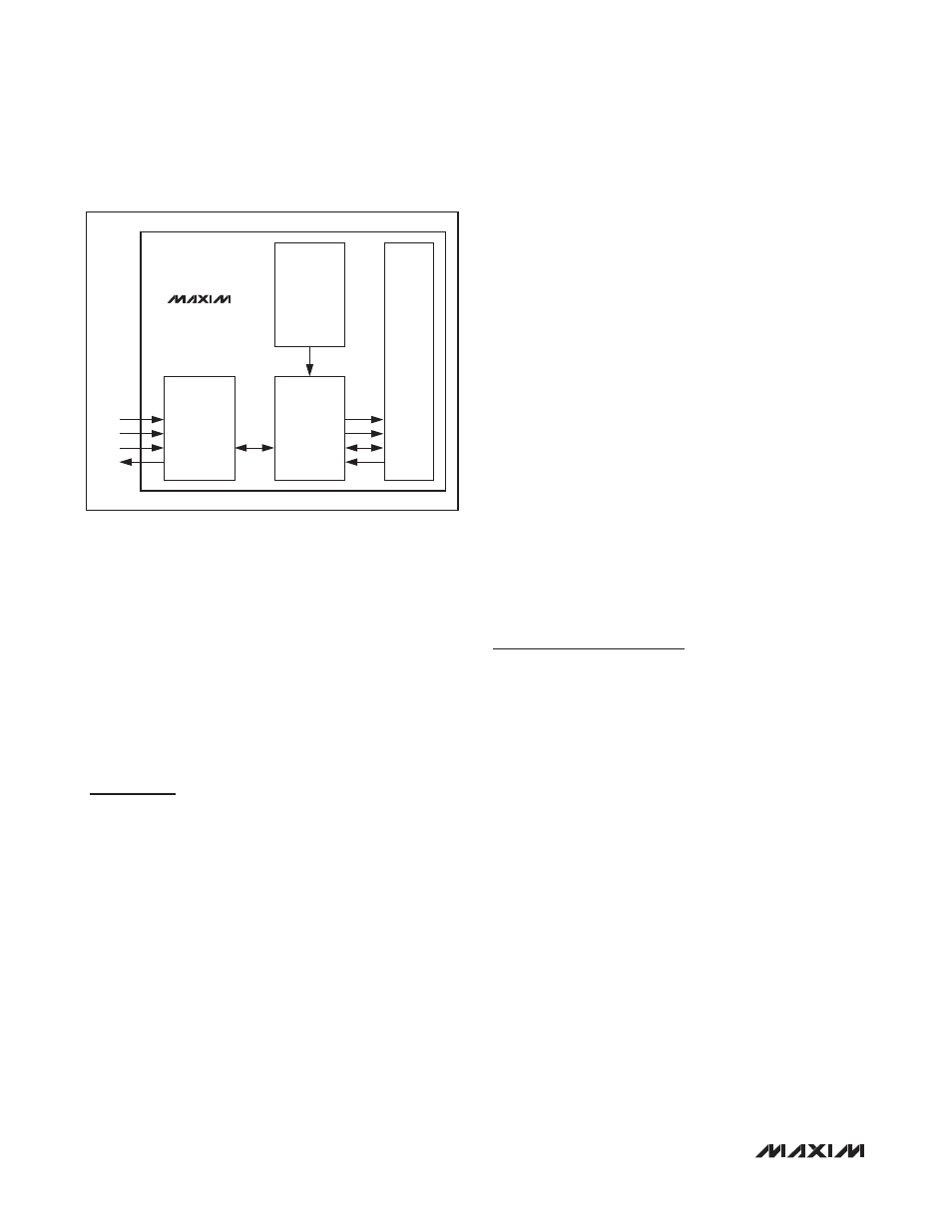
Figure 10. In-Circuit Debugger
TAP
CONTROLLER
CPU
DEBUG
ENGINE
DEBUG
SERVICE
ROUTINES
(UTILITY ROM)
CONTROL
BREAKPOINT
ADDRESS
DATA
MAXQ613
TMS
TCK
TDI
TDO