Ir receive, Figure 4. external irtxm (modulator) output, Bit microcontroller with infrared module maxq613 – Rainbow Electronics MAXQ613 User Manual
Page 17
16-Bit Microcontroller with Infrared Module
MAXQ613
______________________________________________________________________________________ 17
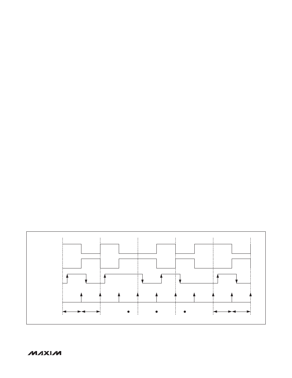
Figure 4. External IRTXM (Modulator) Output
timer value reloads its value. When the IRV reaches 0000h
value, on the next carrier clock, it does the following:
1) Reloads IRV with IRMT.
2) Samples IRCA, IRDATA, and IRTXPOL.
3) Generates IRTX accordingly.
4) Sets IRIF to 1.
5) Generates an interrupt to the CPU if enabled (IRIE = 1).
To terminate the current transmission, the user can
switch to receive mode (IRMODE = 0) or clear IREN to 0.
Carrier Modulation Time = IRMT + 1 carrier cycles
IR Transmit—Independent External Carrier
and Modulator Outputs
The normal transmit mode modulates the carrier based
upon the IRDATA bit. However, the user has the option
to input the modulator (envelope) on an external pin if
desired. If the IRENV[1:0] bits are configured to 01b or
10b, the modulator/envelope is output to the IRTXM pin.
The IRDATA bit is output directly to the IRTXM pin (if
IRTXPOL = 0) on each IRV down-count interval bound-
ary just as if it were being used to internally modulate
the carrier frequency. If IRTXPOL = 1, the inverse of
the IRDATA bit is output to the IRTXM pin on the IRV
interval down-count boundaries. See Figure 4. When
the envelope mode is enabled, it is possible to output
either the modulated (IRENV[1:0] = 01b) or unmodulated
(INENV[1:0] = 10b) carrier to the IRTX pin.
IR Receive
When configured in receive mode (IRMODE = 0), the
IR hardware supports the IRRX capture function. The
IRRXSEL[1:0] bits define which edge(s) of the IRRX pin
should trigger the IR timer capture function.
The IR module starts operating in the receive mode when
IRMODE = 0 and IREN = 1. Once started, the IR timer
(IRV) starts up counting from 0000h when a qualified
capture event as defined by IRRXSEL happens. The IRV
register is, by default, counting carrier cycles as defined
by the IRCA register. However, the IR carrier frequency
detect (IRCFME) bit can be set to 1 to allow clocking of
the IRV register directly with the IRCLK for finer resolu-
tion. When IRCFME = 0, the IRCA defined carrier is
counted by IRV. When IRCFME = 1, the IRCLK clocks
the IRV register.
On the next qualified event, the IR module does the
following:
1) Captures the IRRX pin state and transfers its value
to IRDATA. If a falling edge occurs, IRDATA = 0. If a
rising edge occurs, IRDATA = 1.
2) Transfers its current IRV value to the IRMT.
3) Resets IRV content to 0000h (if IRXRL = 1).
4) Continues counting again until the next qualified event.
If the IR timer value rolls over from 0FFFFh to 0000h
before a qualified event happens, the IR timer overflow
(IROV) flag is set to 1 and an interrupt is generated, if
IRDATA
IR INTERRUPT
IRV INTERVAL
IRTXM
IRTXPOL = 1
IRTXM
IRTXPOL = 0
IRMT
IRMT
IRMT
IRMT
0
1
0
1
0
1
0
1