Bit microcontroller with infrared module maxq613, Pin description (continued) – Rainbow Electronics MAXQ613 User Manual
Page 11
16-Bit Microcontroller with Infrared Module
MAXQ613
______________________________________________________________________________________ 11
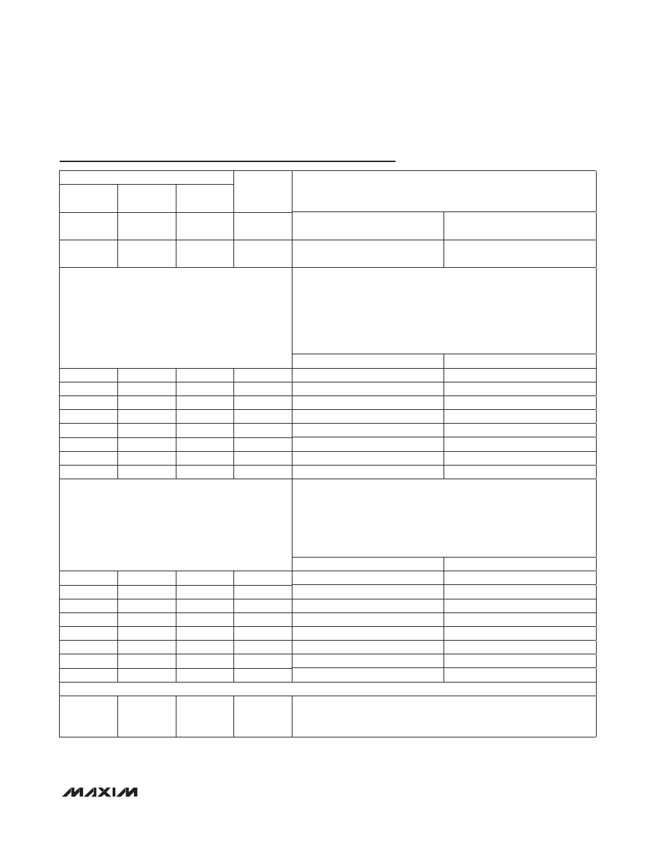
Pin Description (continued)
PIN
NAME
FUNCTION
BARE DIE
32 TQFN-
EP/LQFP
44 TQFN-
EP/TQFP
7
7
9
P0.6/TBB0/
INT14
P0.6
Type B Timer 0 Pin B/INT14
8
8
10
P0.7/TBB1/
INT15
P0.7
Type B Timer 1 Pin B/INT15
Port 1 General-Purpose, Digital I/O Pins with Interrupt Capability. These
port pins function as general-purpose I/O pins with their input and out-
put states controlled by the PD1, PO1, and PI1 registers. All port pins
default to high-impedance mode after a reset. Software must configure
these pins after release from reset to remove the high-impedance con-
dition. All external interrupts must be enabled from software before they
can be used.
GPIO PORT PIN
EXTERNAL INTERRUPT
9
9
11
P1.0/INT0
P1.0
INT0
10
10
12
P1.1/INT1
P1.1
INT1
11
11
13
P1.2/INT2
P1.2
INT2
12
12
14
P1.3/INT3
P1.3
INT3
17
16
21
P1.4/INT4
P1.4
INT4
18
17
22
P1.5/INT5
P1.5
INT5
22
20
25
P1.6/INT6
P1.6
INT6
23
21
26
P1.7/INT7
P1.7
INT7
Port 2 General-Purpose, Digital I/O Pins. These port pins function as
general-purpose I/O pins with their input and output states controlled by
the PD2, PO2, and PI2 registers. All port pins default to high-impedance
mode after a reset. Software must configure these pins after release
from reset to remove the high-impedance condition. All special func-
tions must be enabled from software before they can be used.
GPIO PORT PIN
SPECIAL FUNCTION
24
—
27
P2.0/MOSI
P2.0
SPI: Master Out-Slave In
26
—
29
P2.1/MISO
P2.1
SPI: Master In-Slave Out
28
—
32
P2.2/SCLK
P2.2
SPI: Slave Clock
30
—
33
P2.3/SSEL
P2.3
SPI: Active-Low Slave Select
31
24
34
P2.4/TCK
P2.4
JTAG: Test Clock
32
25
35
P2.5/TDI
P2.5
JTAG: Test Data In
33
26
38
P2.6/TMS
P2.6
JTAG: Test Mode Select
34
27
39
P2.7/TDO
P2.7
JTAG: Test Data Out
NO CONNECTION PINS
—
23
2, 4, 15, 16,
30, 31, 36,
37
N.C.
No Connection. Not internally connected.