Spi electrical characteristics, Bit microcontroller with infrared module maxq613, Recommended operating conditions (continued) – Rainbow Electronics MAXQ613 User Manual
Page 6
16-Bit Microcontroller with Infrared Module
MAXQ613
6 ______________________________________________________________________________________
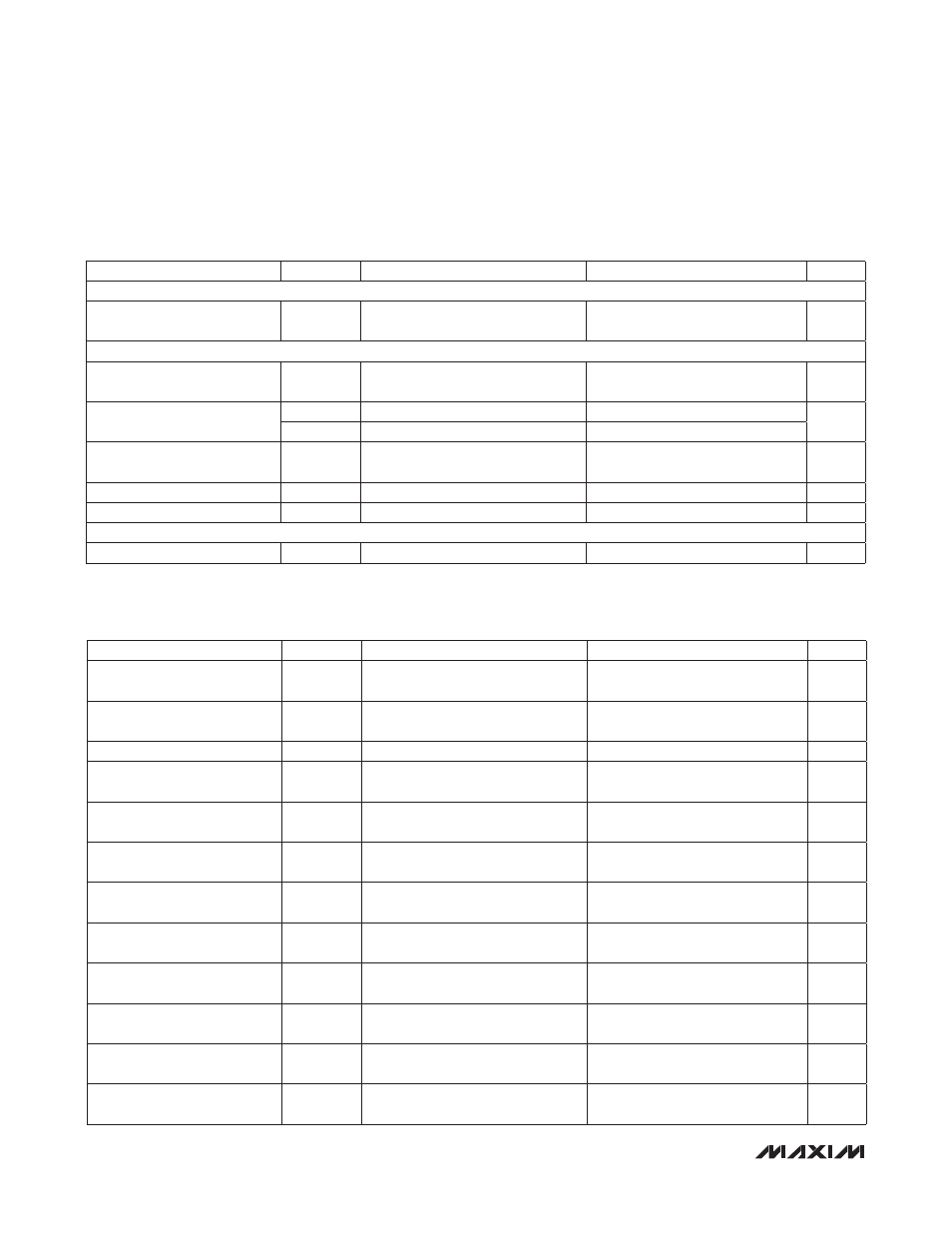
RECOMMENDED OPERATING CONDITIONS (continued)
(V
DD
= V
RST
to 3.6V, T
A
= 0NC to +70NC, unless otherwise noted.) (Note 1)
SPI ELECTRICAL CHARACTERISTICS
(V
DD
= V
RST
to 3.6V, T
A
= 0NC to +70NC, unless otherwise noted.) (Note 11)
PARAMETER
SYMBOL
CONDITIONS
MIN
TYP
MAX
UNITS
WAKE-UP TIMER
Wake-Up Timer Interval
t
WAKEUP
1/f
NANO
65,535/
f
NANO
s
FLASH MEMORY
System Clock During Flash
Programming/Erase
f
FPSYSCLK
6
MHz
Flash Erase Time
t
ME
Mass erase
20
40
ms
t
ERASE
Page erase
20
40
Flash Programming Time per
Word
t
PROG
(Note 10)
20
100
F
s
Write/Erase Cycles
20,000
Cycles
Data Retention
T
A
= +25NC
100
Years
IR
Carrier Frequency
f
IR
(Note 4)
f
CK
/2
Hz
PARAMETER
SYMBOL
CONDITIONS
MIN
TYP
MAX
UNITS
SPI Master Operating
Frequency
1/t
MCK
f
CK
/2
MHz
SPI Slave Operating
Frequency
1/t
SCK
f
CK
/4
MHz
SPI I/O Rise/Fall Time
t
SPI_RF
C
L
= 15pF, pullup = 560
W
8.3
23.6
ns
SCLK Output Pulse-Width
High/Low
t
MCH
, t
MCL
t
MCK
/2 -
t
SPI_RF
ns
MOSI Output Hold Time After
SCLK Sample Edge
t
MOH
t
MCK
/2 -
t
SPI_RF
ns
MOSI Output Valid to Sample
Edge
t
MOV
t
MCK
/2 -
t
SPI_RF
ns
MISO Input Valid to SCLK
Sample Edge Rise/Fall Setup
t
MIS
25
ns
MISO Input to SCLK Sample
Edge Rise/Fall Hold
t
MIH
0
ns
SCLK Inactive to MOSI
Inactive
t
MLH
t
MCK
/2 -
t
SPI_RF
ns
SCLK Input Pulse-Width High/
Low
t
SCH
, t
SCL
t
SCK
/2
ns
SSEL Active to First Shift
Edge
t
SSE
t
SPI_RF
ns
MOSI Input to SCLK Sample
Edge Rise/Fall Setup
t
SIS
t
SPI_RF
ns