Bit microcontroller with infrared module maxq613 – Rainbow Electronics MAXQ613 User Manual
Page 16
16-Bit Microcontroller with Infrared Module
MAXQ613
16 _____________________________________________________________________________________
IRTX pin is set to a logic-high when the IR timer module is
enabled. If IRTXPOL = 0, the IRTX pin is set to a logic-low
when the IR timer is enabled.
A separate register bit, IR data (IRDATA), is used to
determine whether the carrier generator output is output
to the IRTX pin for the next IRMT carrier cycles. When
IRDATA = 1, the carrier waveform (or inversion of this
waveform if IRTXPOL = 1) is output on the IRTX pin dur-
ing the next IRMT cycles. When IRDATA = 0, the idle
condition, as defined by IRTXPOL, is output on the IRTX
pin during the next IRMT cycles.
The IR timer acts as a down counter in transmit mode. An
IR transmission starts when the IREN bit is set to 1 when
IRMODE = 1; when the IRMODE bit is set to 1 when IREN
= 1; or when IREN and IRMODE are both set to 1 in the
same instruction. The IRMT and IRCA registers, along
with the IRDATA and IRTXPOL bits, are sampled at the
beginning of the transmit process and every time the IR
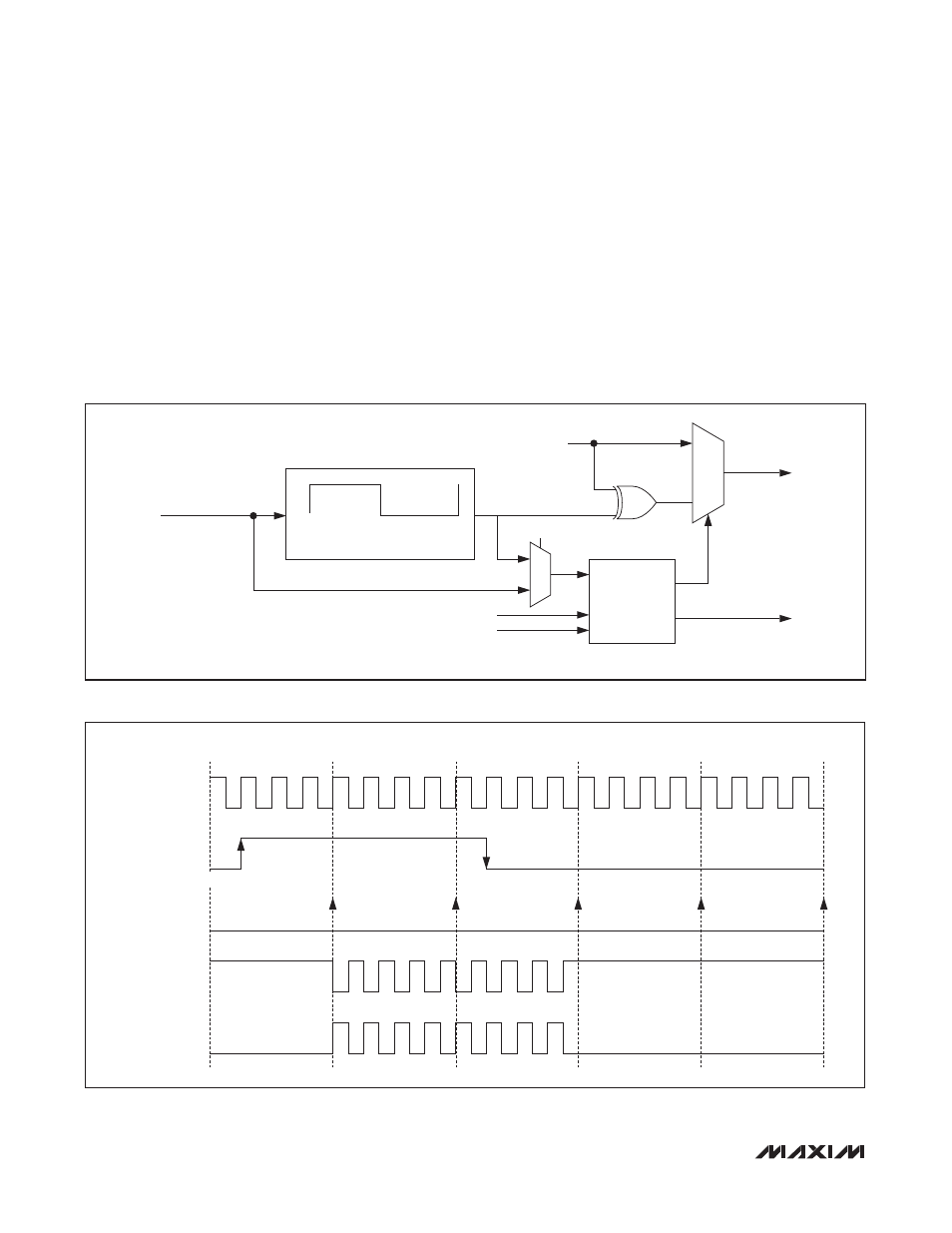
Figure 2. IR Transmit Carrier Generation and Carrier Modulator Control
Figure 3. IR Transmission Waveform (IRCFME = 0)
1
0
0
1
SAMPLE
IRDATA ON
IRV = 0000h
CARRIER MODULATION
CARRIER GENERATION
CARRIER
IRCLK
IRCFME
IRCAL + 1
IRCAH + 1
IRDATA
IRMT
IRTXPOL
IRTX PIN
IR INTERRUPT
CARRIER OUTPUT
(IRV)
IRDATA
IR INTERRUPT
IRTX
IRTXPOL = 1
IRTX
IRTXPOL = 0
0
1
0
IRMT = 3
2
3
1
0
2
3
1
0