General-purpose i/o, On-chip oscillator, Rom loader – Rainbow Electronics MAXQ613 User Manual
Page 21: Loading flash memory, In-application flash programming, Figure 9. on-chip oscillator, Bit microcontroller with infrared module maxq613
16-Bit Microcontroller with Infrared Module
MAXQ613
______________________________________________________________________________________ 21
General-Purpose I/O
The microcontroller provides port pins for general-pur-
pose I/O that have the following features:
• CMOS output drivers
• Schmitt trigger inputs
• Optional weak pullup to V
DD
when operating in input
mode
While the microcontroller is in a reset state, all port pins
become high impedance with both weak pullups and
input buffers disabled, unless otherwise noted.
From a software perspective, each port appears as a
group of peripheral registers with unique addresses.
Special function pins can also be used as general-pur-
pose I/O pins when the special functions are disabled.
For a detailed description of the special functions avail-
able for each pin, refer to the MAXQ610 User’s Guide.
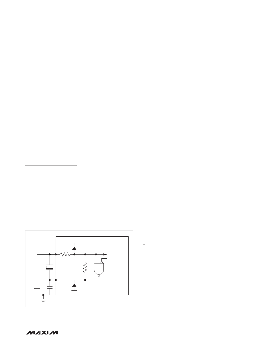
On-Chip Oscillator
An external quartz crystal or a ceramic resonator can be
connected between HFXIN and HFXOUT, as illustrated
in Figure 9.
Noise at HFXIN and HFXOUT can adversely affect on-
chip clock timing. It is good design practice to place the
crystal and capacitors near the oscillator circuitry and
connect HFXIN and HFXOUT to ground with a direct
short trace. The typical values of external capacitors vary
with the type of crystal to be used and should be initially
selected based on load capacitance as suggested by
the manufacturer.
ROM Loader
The ROM loader denies access to the system, user load-
er, or user-application memories unless an area-specific
password is provided. The ROM loader is not available
in ROM-only versions.
Loading Flash Memory
An internal bootstrap loader allows reloading over a
simple JTAG interface. As a result, software can be
upgraded in-system, eliminating the need for a costly
hardware retrofit when updates are required. Remote
software uploads are possible that enable physically
inaccessible applications to be frequently updated. The
interface hardware can be a JTAG connection to another
microcontroller, or a connection to a PC serial port using
a serial-to-JTAG converter such as the MAXQJTAG-001,
available from Maxim. If in-system programmability is not
required, a commercial gang programmer can be used
for mass programming. Activating the JTAG interface
and loading the test access port (TAP) with the system
programming instruction invokes the bootstrap loader.
Setting the SPE bit to one during reset through the JTAG
interface executes the bootstrap-loader mode program
that resides in the utility ROM. When programming is
complete, the bootstrap loader can clear the SPE bit and
reset the device, allowing the device to bypass the utility
ROM and begin execution of the application software.
In addition, the ROM loader also enforces the memory-
protection policies. Passwords that are 16 words are
required to access the ROM loader interface.
Loading memory is not possible for ROM-only versions
of the device.
In-Application Flash Programming
From user-application code, flash memory can be pro-
grammed using the ROM utility functions from either C
or assembly language. The function declarations below
show examples of some of the ROM utility functions
provided for in-application flash memory programming:
/* Write one 16-bit word to code address ‘dest’.
* Dest must be aligned to 16 bits.
* Returns 0 = failure, 1 = OK.
*/
int flash_write (uint16_t dest, uint16_t
data);
Figure 9. On-Chip Oscillator
V
DD
HFXIN
CLOCK CIRCUIT
R
F
= 1MI Q50%
C1 = C2 = 12pF
STOP
HFXOUT
C2
C1
R
F