Power-fail detection, Bit microcontroller with infrared module maxq613 – Rainbow Electronics MAXQ613 User Manual
Page 23
16-Bit Microcontroller with Infrared Module
MAXQ613
______________________________________________________________________________________ 23
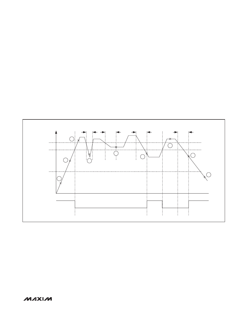
Power-Fail Detection
Figures 11, 12, and 13 show the power-fail detection and
response during normal and stop-mode operation. If a
reset is caused by a power-fail, the power-fail monitor
can be set to one of the following intervals:
• Always on—continuous monitoring
• 2
11
nanopower ring oscillator clocks (~256ms)
• 2
12
nanopower ring oscillator clocks (~512ms)
• 2
13
nanopower ring oscillator clocks (~1.024s)
In the case where the power-fail circuitry is periodically
turned on, the power-fail detection is turned on for two
nanopower ring-oscillator cycles. If V
DD
> V
RST
during
detection, V
DD
is monitored for an additional nanopower
ring-oscillator period. If V
DD
remains above V
RST
for
the third nanopower ring period, the CPU exits the reset
state and resumes normal operation from utility ROM at
8000h after satisfying the crystal warmup period.
If a reset is generated by any other event, such as the
RESET pin being driven low externally or the watchdog
timer, the power-fail, internal regulator, and crystal
remain on during the CPU reset. In these cases, the CPU
exits the reset state in less than 20 crystal cycles after
the reset source is removed.
Figure 11. Power-Fail Detection During Normal Operation
A
B
C
D
F
G
H
I
E
V
DD
V
PFW
V
RST
V
POR
INTERNAL RESET
(ACTIVE HIGH)
t
< t
PFW
t
≥ t
PFW
t
≥ t
PFW
t
≥ t
PFW