Rainbow Electronics MAX9216 User Manual
Page 11
MAX9210/MAX9212/MAX9214/MAX9216/MAX9220/MAX9222
Programmable DC-Balance
21-Bit Deserializers
______________________________________________________________________________________
11
Jitter due to droop is proportional to the droop and
transition time:
t
J
= t
T
x D (Eq 2)
where:
t
J
= jitter (s)
t
T
= transition time (s) (0% to 100%)
D = droop (% of signal amplitude)
Jitter due to 2% droop and assumed 1ns transition time is:
t
J
= 1ns x 0.02
t
J
= 20ps
The transition time in a real system depends on the fre-
quency response of the cable driven by the serializer.
The capacitor value decreases for a higher frequency
parallel clock and for higher levels of droop and jitter.
Use high-frequency, surface-mount ceramic capacitors.
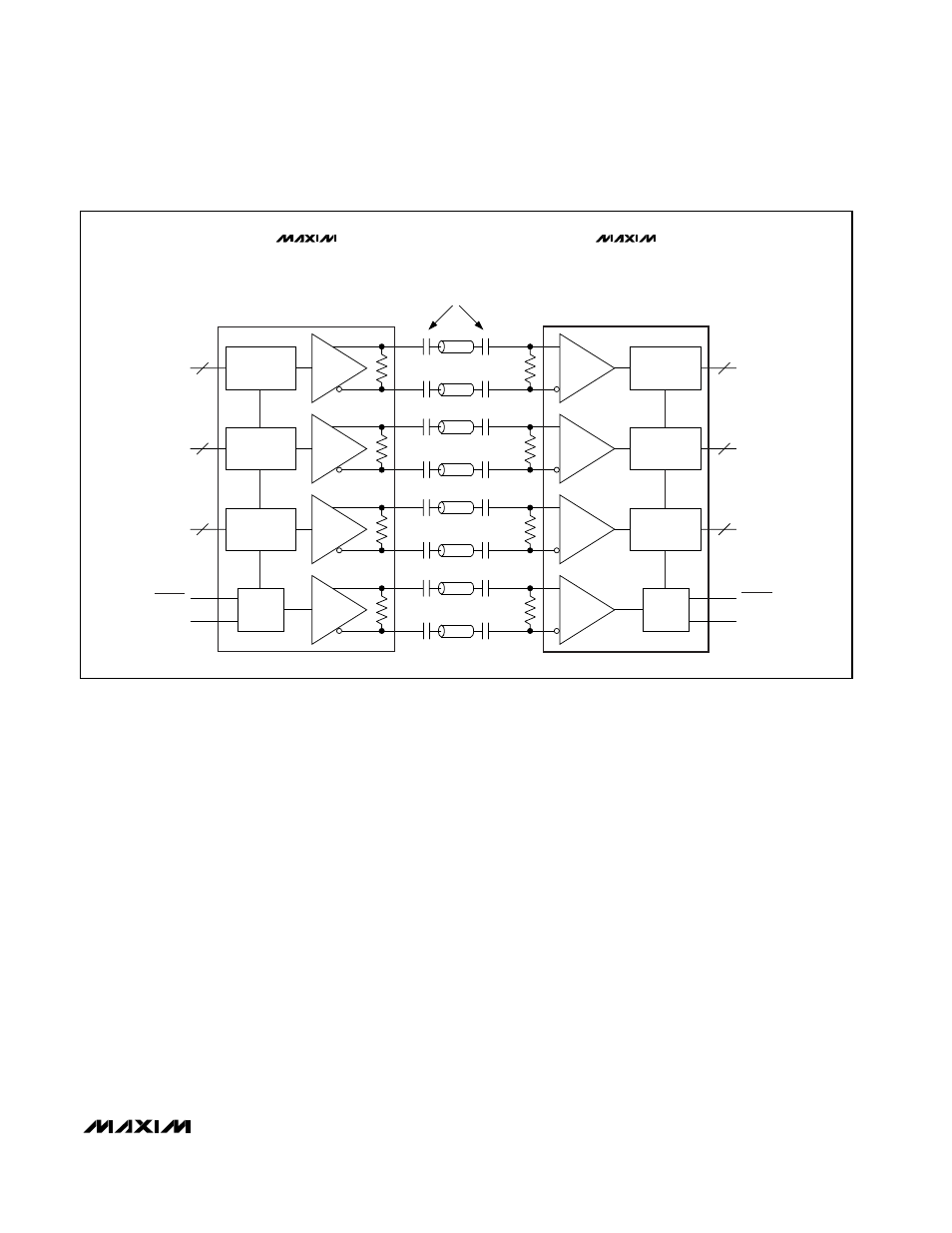
Equation 1 altered for four series capacitors (Figure 13) is:
C = - (4 x t
B
x DSV) / (ln (1 - D) x (R
T
+ R
O
)) (Eq 3)
Fail-Safe
The MAX9210/MAX9212/MAX9214/MAX9216/MAX9220/
MAX9222 have fail-safe LVDS inputs in non-DC-bal-
anced mode (Figure 1). Fail-safe drives the outputs low
when the corresponding LVDS input is open, undriven
and shorted, or undriven and parallel terminated. The
fail-safe on the LVDS clock input drives all outputs low.
Fail-safe does not operate in DC-balanced mode.
Input Bias and Frequency Detection
In DC-balanced mode, the inverting and noninverting
LVDS inputs are internally connected to +1.2V through
42k
Ω (min) to provide biasing for AC-coupling (Figure 1).
A frequency-detection circuit on the clock input detects
when the input is not switching, or is switching at low
frequency. In this case, all outputs are driven low. To
prevent switching due to noise when the clock input is
not driven, bias the clock input to differential +15mV by
connecting a 10k
Ω ±1% pullup resistor between the
noninverting input and V
CC
, and a 10k
Ω ±1% pulldown
resistor between the inverting input and ground. These
(7 + 2):1
1:(9 - 2)
7
7
100
Ω
(7 + 2):1
1:(9 - 2)
7
7
100
Ω
(7 + 2):1
1:(9 - 2)
7
7
100
Ω
PLL
PLL
100
Ω
MAX9209
MAX9211
MAX9213
MAX9215
MAX9210
MAX9212
MAX9214
MAX9216
MAX9220
MAX9222
TxOUT
TxCLK OUT
RxIN
RxCLK IN
21:3 SERIALIZER
3:21 DESERIALIZER
PWRDWN
RxCLK OUT
RxOUT
PWRDWN
TxCLK IN
TxIN
HIGH-FREQUENCY, CERAMIC
SURFACE-MOUNT CAPACITORS
Figure 13. Four Capacitors per Link, AC-Coupled, DC-Balanced Mode