Pin description – Rainbow Electronics MAX5440 User Manual
Page 6
MAX5440
Stereo Volume Control
with Rotary Encoder Interface
6
_______________________________________________________________________________________
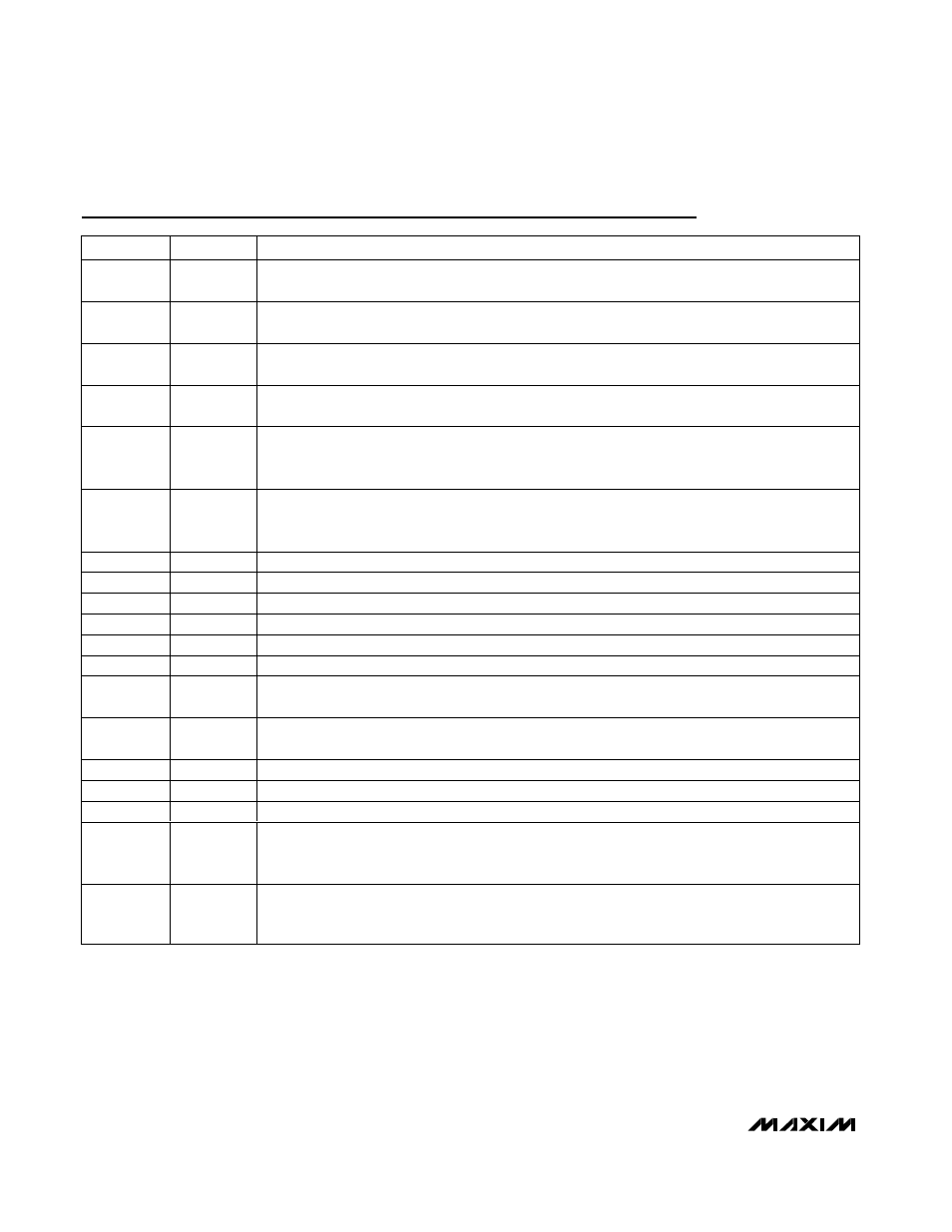
PIN
NAME
FUNCTION
1
V
LOGIC
Digital Logic Power Supply. Bypass V
LOGIC
to ground with a 0.1µF capacitor as close to the device
as possible.
2
RENCODEA
Rotary Encoder Input A. With RENCODEB, this input provides the rotary encoder control for the
potentiometer (see Figure 1). RENCODEA is internally pulled up to V
LOGIC
with a 45k
Ω resistor.
3
RENCODEB
Rotary Encoder Input B. With RENCODEA, this input provides the rotary encoder control for the
potentiometer (see Figure 1). RENCODEB is internally pulled up to V
LOGIC
with a 45k
Ω resistor.
4
MUTE
Mute Input. Pull MUTE low to toggle the wiper between the mute setting (see Table 1) and the current
setting. MUTE is pulled up to V
LOGIC
with an internal 45k
Ω resistor.
5
MODE
Volume/Balance Control Input. Each high-to-low transition on MODE toggles between the volume and
balance modes. MODE is pulled high internally with a 45k
Ω resistor to V
LOGIC
. On power-up, the
MAX5440 is in volume-control mode.
6
SHDN
Active-Low Shutdown Input. Drive SHDN low to place the device in shutdown mode. In shutdown
mode, the MAX5440 stores the last wipers settings. The wipers move to the L_ end of the resistor
string. Terminating shutdown mode restores the wipers to their previous settings.
7, 24
GND
Ground. Connect pins 7 and 24 together.
8
H0
Potentiometer 0 High Terminal. H0 and L0 terminals can be reversed.
9
L0
Potentiometer 0 Low Terminal. L0 and H0 terminals can be reversed.
10
W0
Potentiometer 0 Wiper Buffered Output
11
MIDBIAS
Midbias Voltage Output. V
MIDBIAS
= (V
DD
+ V
SS
) / 2.
12
BIAS
Bias Generator Input. Bypass with a 1µF capacitor to system ground.
13
V
DD
Analog Power Supply. Bypass V
DD
to ground with a 0.1µF capacitor as close to the device as
possible.
14
V
SS
Negative Power Supply. Bypass V
SS
to ground with a 0.1µF capacitor as close to the device as
possible. Connect to GND for single-supply operation.
15
W1
Potentiometer 1 Wiper Buffered Output
16
L1
Potentiometer 1 Low Terminal. L1 and H1 terminals can be reversed.
17
H1
Potentiometer 1 High Terminal. H1 and L1 terminals can be reversed.
18–22
LEDIND0–
LEDIND4
LE D Ind i cator O p en- D r ai n Outp ut 0 thr oug h LE D Ind i cator O p en- D r ai n Outp ut 4. LE D IN D 0–LE D IN D 4 for m a
b ar g r ap h i nd i cati on of the cur r ent vol um e or b al ance. In vol um e m od e, al l LE D s off i nd i cates m ute and al l
LE D s on i nd i cates m axi m um vol um e. In b al anced m od e, LE D 2 on i nd i cates center ed or b al anced .
23
MODEIND
Volume-Control/Balance-Control Mode Indicator Open-Drain Output. Connect to an LED through a
resistor to V
LOGIC
. When the LED is on, the MAX5440 is in balance-control mode. When the LED is
off, the MAX5440 is in volume-control mode.
Pin Description