Th7834c – Rainbow Electronics TH7834C User Manual
Page 7
7
TH7834C
1997A–IMAGE–05/02
•
Each video line in four output operating mode consists in:
–
30 inactive pre-scan, (not connected to pixels),
–
6 dark references,
–
4 isolation elements, (inactive, not connected to pixels),
–
3 non-useful pixels,
–
3 000 useful pixels of the line.
N = number of pixel periods (T
p
) during readout period (see Figure 5).
Four output operating mode: N
≥
3043.
Two output operating mode: N
≥
6086.
(
Φ
LS
can be clocked during the line blancking).
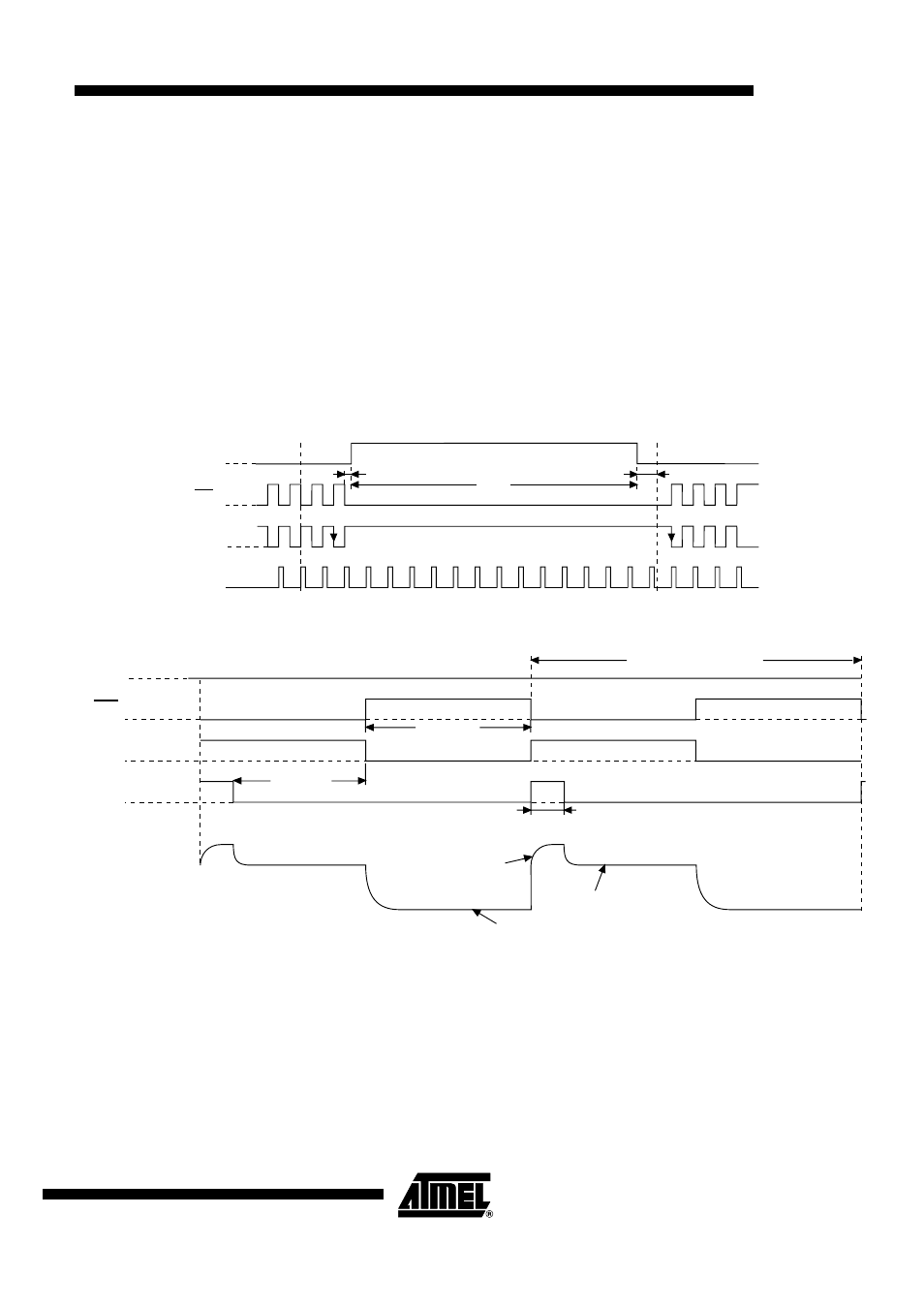
Figure 4. Detailed Timing Diagram For Transfer From Photosite To Register
Figure 5. Detailed Pixel Timing Diagram
T
P
= Pixel period
Rise and fall time:
Φ
R1-2
,
Φ
R3-4
: 5% of T
P
(min. 5 ns),
Φ
LS1-2
,
Φ
LS3-4
: 5% of T
P
(min. 5 ns),
Φ
L1
,
Φ
L2
: 25% of TP (min. 30 ns),
Φ
P1-2
,
Φ
P3-4
: 100 ns (min 20 ns).
≥
20 ns
N
1
≥
100 ns
≥
2
µ
s
Φ
P1-2,
Φ
P3-4
Φ
LS
Φ
R
Φ
L1,
Φ
L2
≥
20 ns
≥
30 ns
Reset
Signal
Φ
P1-2,
Φ
P3-4
Φ
L1,
Φ
L2
Φ
LS1-2,
Φ
LS3-4
Φ
R1-2,
Φ
R3-4
VOS (1-2-3-4)
(CCD output signal)
Floating
diode
(Reference level for
correlated double Sampling)
Tp (200 ns Typ.)
Tp/2 Typ.