Bit shift mode (mcl compatible), Figure 65, Figure 66 – Rainbow Electronics T48C862-R8 User Manual
Page 70
70
T48C862-R8
4590B–4BMCU–02/03
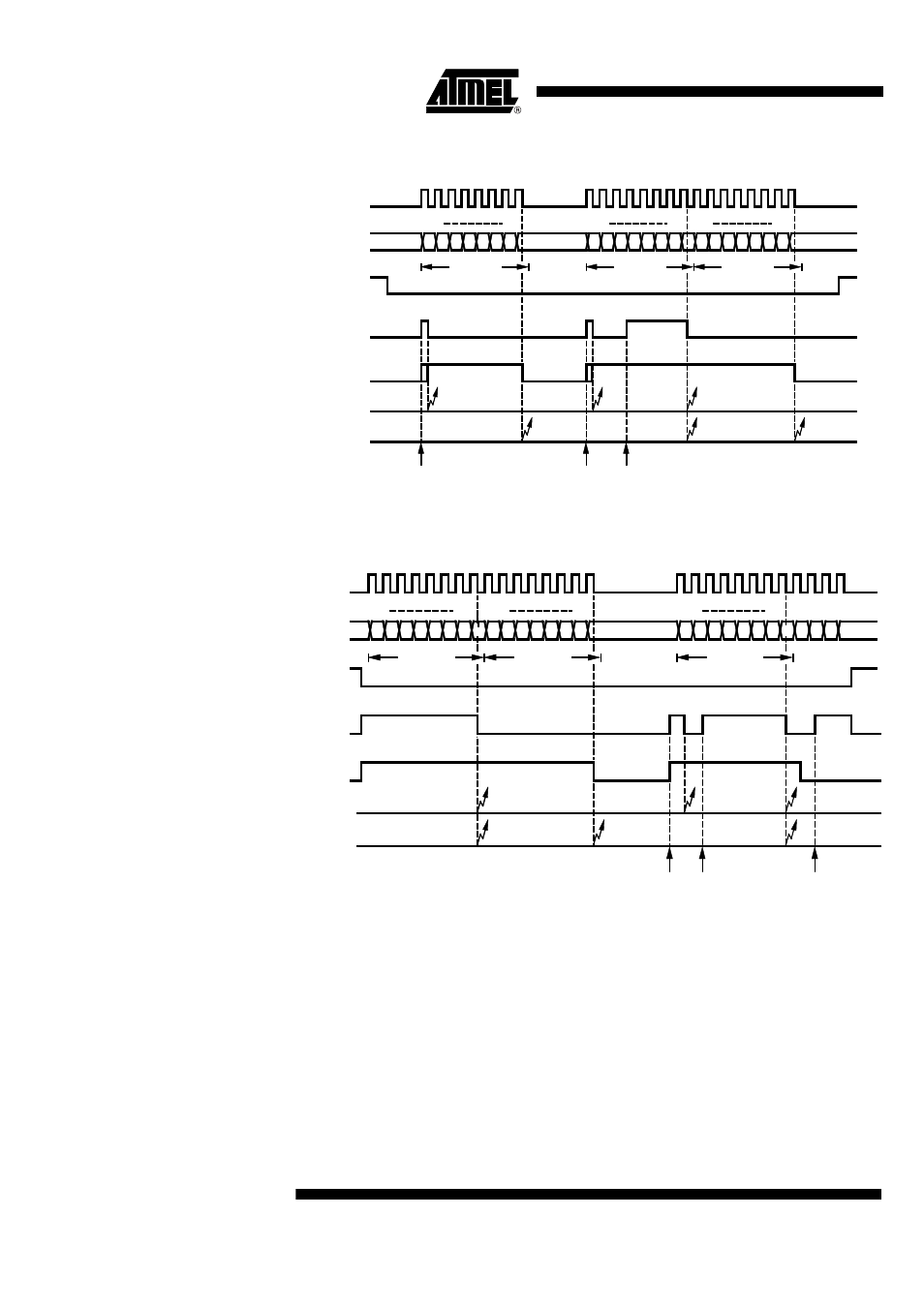
Figure 65.
Example of 8-bit Synchronous Transmit Operation
Figure 66.
Example of 8-bit Synchronous Receive Operation
9-bit Shift Mode
(MCL compatible)
In the 9-bit shift mode, the SSI is able to handle the MCL protocol (described below). It
always operates as an MCL master device, i.e., SC is always generated and output by
the SSI. Both the MCL start and stop conditions are automatically generated whenever
the SSI is activated or deactivated by the SIR-bit. In accordance with the MCL protocol,
the output data is always changed in the clock low phase and shifted in on the high
phase.
Before activating the SSI (SIR = 0) and commencing an MCL dialog, the appropriate
data direction for the first word must be set using the SDD control bit. The state of this
7 6 5 4 3 2 1
0
7 6 5 4 3 2 1 0 7 6 5 4 3 2 1
0
msb
lsb
tx data 1
tx data 2
tx data 3
msb
lsb msb
lsb
Write STB
(tx data 2)
Write STB
(tx data 3)
Write STB
(tx data 1)
SC
SD
SIR
SRDY
Interrupt
(IFN = 0)
Interrupt
(IFN = 1)
ACT
4 3 2 1 0
7 6 5 4 3 2 1 0
msb
lsb
rx data 1
rx data 2
rx data 3
msb
lsb
msb
lsb
Read SRB
(rx data 2)
Read SRB
(rx data 3)
Read SRB
(rx data 1)
SC
SD
SIR
SRDY
Interrupt
(IFN = 0)
Interrupt
(IFN = 1)
ACT
7 6 5
4 3 2 1 0
7 6 5
7 6 5 4