Digital interface, Table 1. r, At selected codes – Rainbow Electronics MAX5484 User Manual
Page 13
MAX5481–MAX5484
10-Bit, Nonvolatile, Linear-Taper Digital
Potentiometers
______________________________________________________________________________________
13
where D is the decimal equivalent of the 10 data bits writ-
ten (0 to 1023), V
HL
is the voltage difference between the
H and L terminals:
The MAX5481 includes a total end-to-end resistance
value of 10k
Ω while the MAX5482 features an end-to-
end resistance value of 50k
Ω. These devices are not
intended to be used as a variable resistor. Wiper cur-
rent creates a nonlinear voltage drop in series with the
wiper. To ensure temperature drift remains within speci-
fications, do not pull current through the voltage-divider
wiper. Connect the wiper to a high-impedance node.
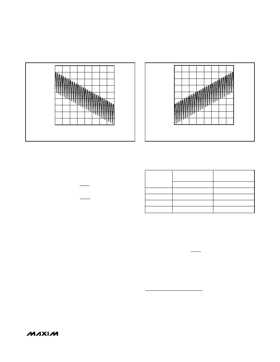
Figures 1 and 2 show the behavior of the MAX5481’s
resistance from W to H and from W to L. This does not
apply to the variable-resistor devices
MAX5483/MAX5484 Variable Resistors
The MAX5483/MAX5484 provide a programmable
resistance between W and L. The MAX5483 features a
total end-to-end resistance value of 10k
Ω, while the
MAX5484 provides an end-to-end resistance value of
50k
Ω. The programmable resolution of this resistance is
equal to the nominal end-to-end resistance divided by
1024 (10-bit resolution). For example, each nominal
segment resistance is 9.8
Ω and 48.8Ω for the MAX5483
and the MAX5484, respectively.
The 10-bit data in the 10-bit latch register selects a
wiper position from the 1024 possible positions, result-
ing in 1024 values for the resistance from W to L.
Calculate the resistance from W to L (R
WL
) by using the
following formula:
where D is decimal equivalent of the 10 data bits writ-
ten, R
W-L
is the nominal end-to-end resistance, and R
Z
is the zero-scale error. Table 1 shows the values of R
WL
at selected codes for the MAX5483/MAX5484.
Digital Interface
Configure the MAX5481–MAX5484 by a pin-selectable,
3-wire, SPI-compatible serial data interface or an
up/down interface. Drive SPI/UD high to select the 3-
wire SPI-compatible interface. Pull SPI/UD low to select
the up/down interface.
R
D
D
R
R
WL
W L
Z
( )
=
×
+
−
1023
V
FSE
V
and
V
ZSE
V
FSE
HL
ZSE
HL
=
⎡
⎣⎢
⎤
⎦⎥
=
⎡
⎣⎢
⎤
⎦⎥
1024
1024
,
MAX5483
(10k
Ω DEVICE)
MAX5484
(50k
Ω DEVICE)
CODE
(DECIMAL)
R
WL
(
Ω)
R
WL
(
Ω)
0
70
110
1
80
160
512
5070
25,110
1023
10,070
50,110
Table 1. R
WL
at Selected Codes
CODE (DECIMAL)
R
W-H
(k
Ω
)
896
768
512 640
256 384
128
2
4
6
8
10
12
14
16
18
0
0
1024
50k
Ω DEVICE SCALES BY A FACTOR OF FIVE
Figure 1. Resistance from W to H vs. Code (10k
Ω Voltage-Divider)
CODE (DECIMAL)
R
W-L
(k
Ω
)
896
768
512 640
256 384
128
2
4
6
8
10
12
14
16
18
0
0
1024
50k
Ω DEVICE SCALES BY A FACTOR OF FIVE
Figure 2. Resistance from W to L vs. Code (10k
Ω Voltage-Divider)