Detailed description, Functional diagrams (continued) – Rainbow Electronics MAX5484 User Manual
Page 12
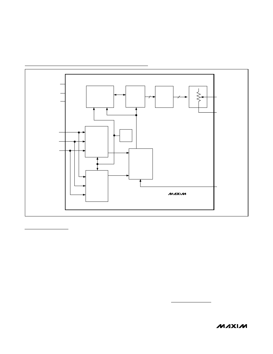
MAX5481–MAX5484
10-Bit, Nonvolatile, Linear-Taper Digital
Potentiometers
12
______________________________________________________________________________________
Detailed Description
The MAX5481/MAX5482 linear programmable voltage-
dividers and the MAX5483/MAX5484 variable resistors
feature 1024 tap points (10-bit resolution) (see the
Functional Diagrams). These devices consist of multi-
ple strings of equal resistor segments with a wiper con-
tact that moves among the 1024 points through a
pin-selectable 3-wire SPI-compatible serial interface or
up/down interface. The MAX5481/MAX5483 provide a
total end-to-end resistance of 10k
Ω, and the
MAX5482/MAX5484 have an end-to-end resistance of
50k
Ω. The MAX5481/MAX5482 allow access to the
high, low, and wiper terminals for a standard voltage-
divider configuration.
MAX5481/MAX5482 Programmable
Voltage-Dividers
The MAX5481/MAX5482 programmable voltage-
dividers provide a weighted average of the voltage
between the H and L inputs at the W output. Both
devices feature 10-bit resolution and provide up to
1024 tap points between the H and L voltages. Ideally,
the V
L
voltage occurs at the wiper terminal (W) when all
data bits are zero and the V
H
voltage occurs at the
wiper terminal when all data bits are one. The step size
(1 LSB) voltage is equal to the voltage applied across
terminals H and L divided by 2
10
. Calculate the wiper
voltage V
W
as follows:
V
D
D
V
V
V
V
V
W
HL
FSE
ZSE
L
ZSE
( )
=
+
(
)
⎡
⎣
⎢
⎢
⎢
⎤
⎦
⎥
⎥
⎥
+
+
−
⏐
⏐ ⏐
⏐
⏐
⏐
1023
MAX5483
MAX5484
SPI/
UD
H
10
10
DECODER
10-BIT
LATCH
10-BIT
NV
MEMORY
POR
SPI
INTERFACE
UP/DOWN
INTERFACE
MUX
DIN(U/
D)
SCLK(
INC)
CS
V
DD
GND
V
SS
L
Functional Diagrams (continued)