Rainbow Electronics RC1290 User Manual
Page 10
RC1240/1280/1290
2005 Radiocrafts AS
RC1240/RC1280/RC1290 Data Sheet (rev. 1.3)
Page 10 of 17
RSSI Reading
The module provide a digital Received Signal Strength Indicator (RSSI) through the ‘S’
command. The module returns an 8 bit character indicating the current input signal strength.
The signal strength can be used as an indication of fading margin, or as a carrier sense signal
to avoid collisions.
Do note that if the signal strength for an incoming packet is to be measured, the ‘S’ command
must be performed while the packet is being received. To simplify the test of a link, and avoid
timing problems, the transmitter can be set to continuous transmission using the ‘2’ test
command, while the receiver use the ‘S’ command to read the signal strength.
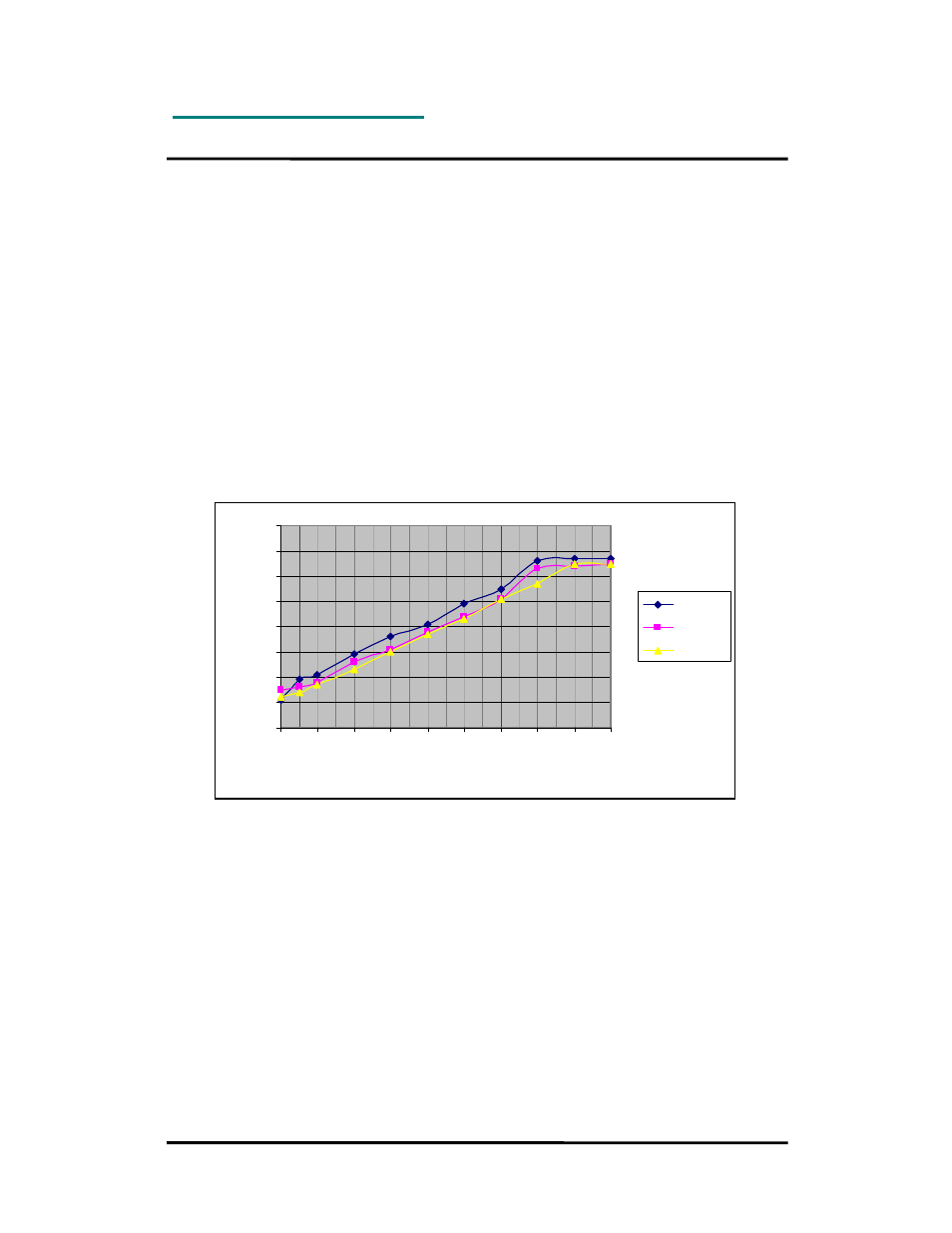
The RSSI value increases with increased input signal strength. Input signal strength is given
by (typ.):
P = 1.5 x RSSI – 144 [dBm] for RC1240
P = 1.5 x RSSI – 137 [dBm] for RC1280
P = 1.5 x RSSI – 138 [dBm] for RC1290
Typical RSSI value as a function of input signal strength is shown in the figure below.
0
10
20
30
40
50
60
70
80
-120 -110 -100 -90 -80 -70 -60 -50 -40 -30
Input power level [dBm]
R
S
S
I v
al
ue
[d
ec
im
al
]
RC1240
RC1280
RC1290