Max6965, Output led driver with intensity control, Functional overview – Rainbow Electronics MAX6965 User Manual
Page 6: Output control and led blinking, Pwm intensity control
MAX6965
Functional Overview
The MAX6965 is a general-purpose output (GPO)
peripheral that provides nine output ports, O0–O8, con-
trolled through an I
2
C-compatible serial interface. All out-
puts sink loads up to 50mA connected to external
supplies up to 7V, independent of the MAX6965’s supply
voltage. The MAX6965 is rated for a ground current of
190mA, allowing all nine outputs to sink 20mA at the
same time. Figure 1 shows the output structure of the
MAX6965. The outputs default to logic high (high imped-
ance unless external pullup resistors are used) on
power-up.
Output Control and LED Blinking
The blink phase 0 register sets the output logic levels of
the 8 outputs O0–O7 (Table 6). This register controls
the port outputs if the blink function is disabled. A dupli-
cate register, the Blink Phase 1 register, is also used if
the blink function is enabled (Table 7). In blink mode,
the outputs can be flipped between using the blink
phase 0 register, and the blink phase 1 register using
hardware control (the BLINK input) and/or software
control (the blink flip flag in the configuration register)
(Table 4).
The 9th output, O8, is controlled through 2 bits in the
Configuration register, which provide the same static or
blink control as the other eight outputs (Table 4).
The logic level of the BLINK input may be read back
through the blink status bit in the configuration register
(Table 4). The BLINK input, therefore, may be used as
a general-purpose logic input (GPI port) if the blink
function is not required.
PWM Intensity Control
The MAX6965 includes an internal oscillator, nominally
32kHz, to generate PWM timing for LED intensity con-
trol. PWM intensity control can be enabled on an out-
put-by-output basis, allowing the MAX6965 to provide
any mix of PWM LED drives and glitch-free logic out-
puts (Table 8). PWM can be disabled entirely, in which
case all outputs are static and the MAX6965 operating
current is lowest because the internal oscillator is
turned off.
PWM intensity control uses a 4-bit master control and 4
bits of individual control per output (Tables 11 and 12).
The 4-bit master control provides 16 levels of overall
intensity control, which applies to all PWM-enabled out-
puts. The master control sets the maximum pulse width
from 1/15 to 15/15 of the PWM time period. The individ-
ual settings comprise a 4-bit number, further reducing
the duty cycle to be from 1/16 to 15/16 of the time win-
dow set by the master control.
For applications requiring the same PWM setting for all
output ports, a single global PWM control can be used
instead of all the individual controls to simplify the con-
trol software and provide 240 steps of intensity control
(Tables 8 and 11).
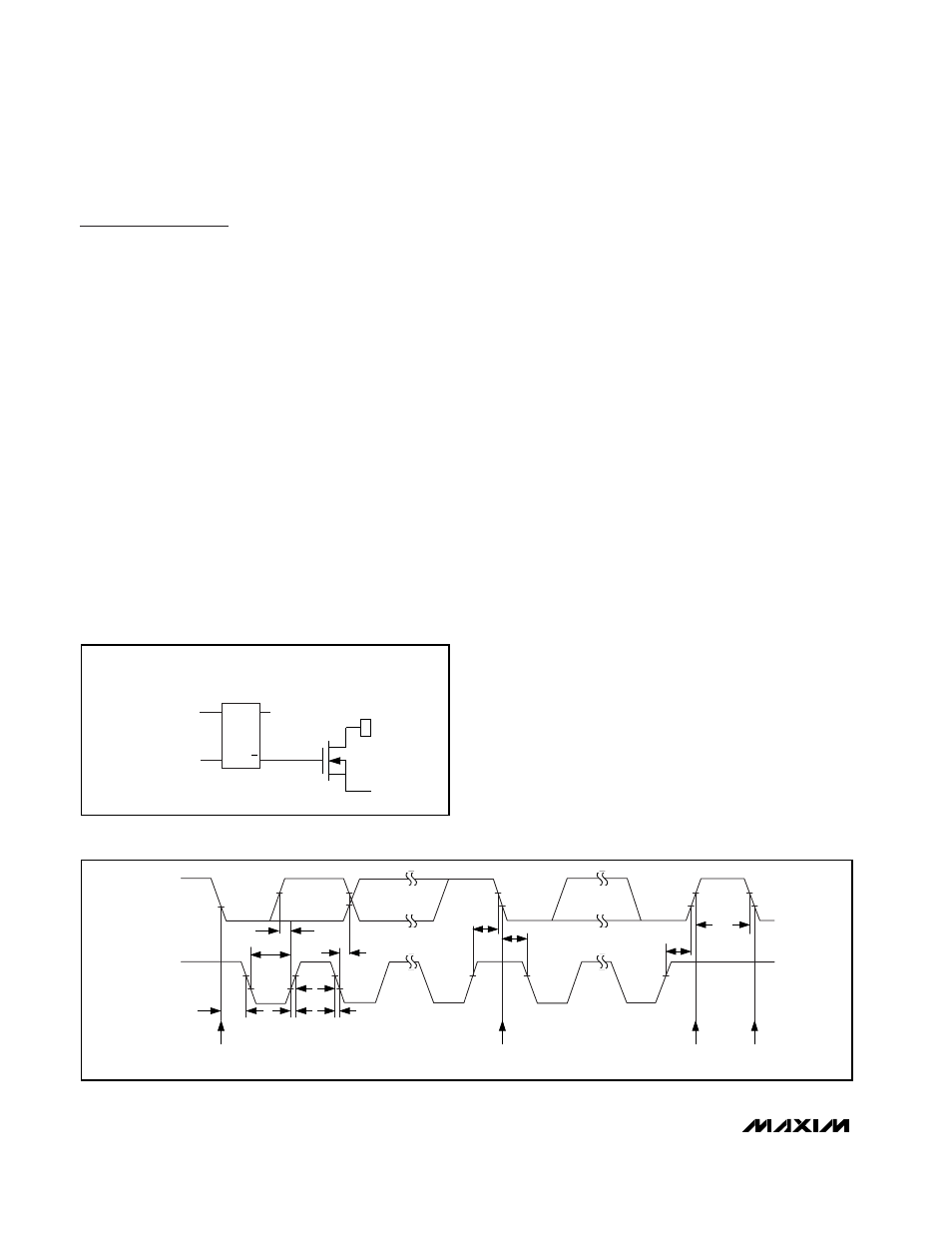
9-Output LED Driver with Intensity Control
6
_______________________________________________________________________________________
Figure 1. Simplified Schematic of I/O Ports
DATA FROM
SHIFT REGISTER
WRITE PULSE
D
C
K
Q
Q
FF
OUTPUT
PORT
REGISTER
I/O PIN
GND
Q2
OUTPUT PORT
REGISTER DATA
Figure 2. 2-Wire Serial Interface Timing Details
SCL
SDA
t
R
t
F
t
BUF
START
CONDITION
STOP
CONDITION
REPEATED START CONDITION
START CONDITION
t
SU,STO
t
HD,STA
t
SU,STA
t
HD,DAT
t
SU,DAT
t
LOW
t
HIGH
t
HD,STA