Table 4. configuration register (continued), Table 5. blink controls – Rainbow Electronics MAX6965 User Manual
Page 12
MAX6965
9-Output LED Driver with Intensity Control
12
______________________________________________________________________________________
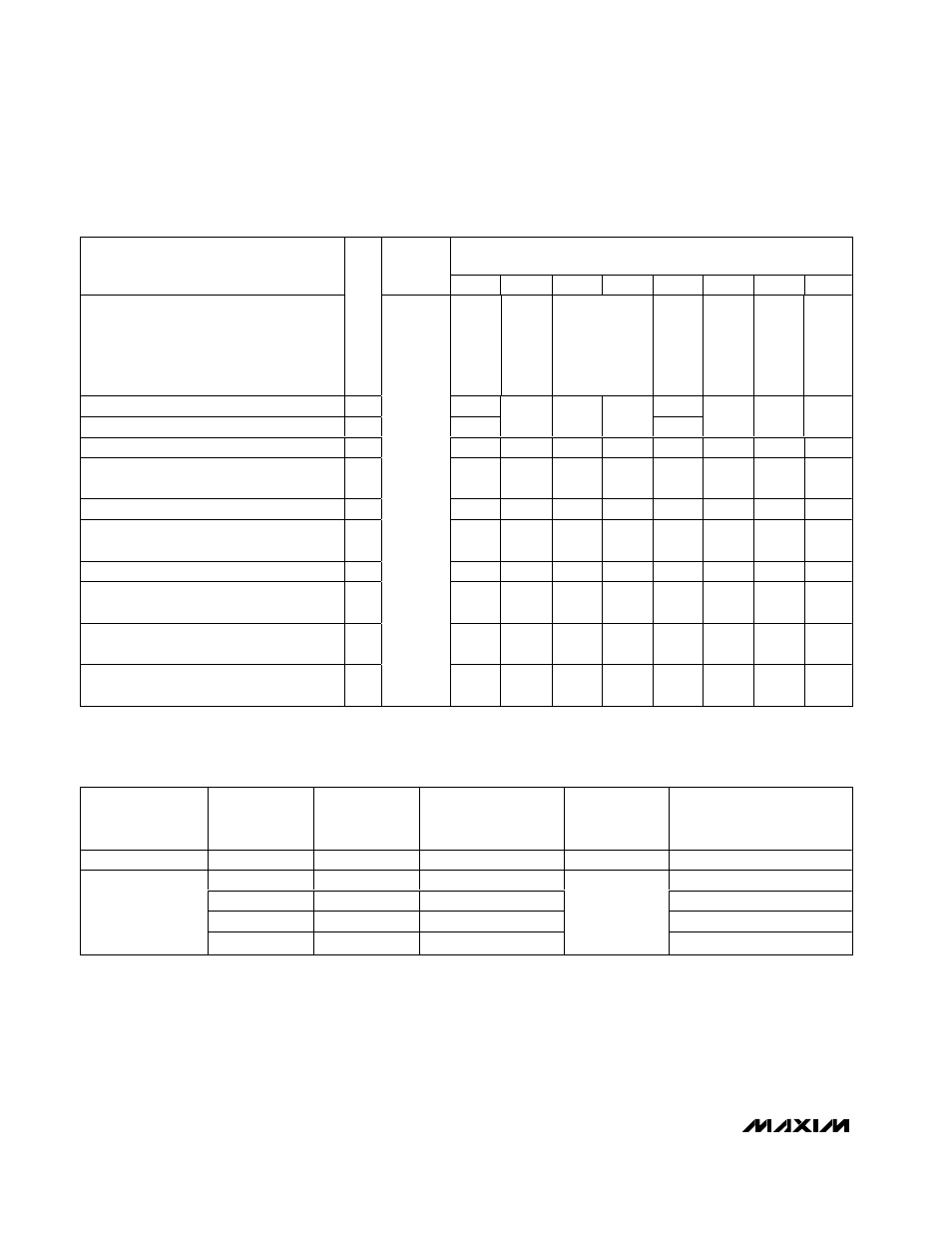
Table 4. Configuration Register (continued)
REGISTER DATA
REGISTER
ADDRESS
CODE
(HEX)
D7
D6
D5
D4
D3
D2
D1
D0
CONFIGURATION
R/W
—
BLINK
STATUS
OUTPUT
O8
—
GLOBAL
INTENSITY
BLINK FLIP
BLINK
ENABLE
Write device configuration
0
X
X
Read-back device configuration
1
0
BLINK
O1
O0
0
G
B
E
O8 output is low (blink is disabled)
—
X
X
X
0
0
X
X
0
O8 output is high impedance
(blink is disabled)
—
X
X
X
1
0
X
X
0
O 8 outp ut i s l ow d ur i ng b l i nk p hase 0
—
0x0F
X
X
X
0
0
X
X
1
O8 output is high impedance during
blink phase 0
—
X
X
X
1
0
X
X
1
O 8 outp ut i s l ow d ur i ng b l i nk p hase 1
—
X
X
0
X
0
X
X
1
O8 output is high impedance during
blink phase 1
—
X
X
1
X
0
X
X
1
Read-back BLINK input pin status;
input is low
1
X
0
X
X
X
X
X
X
Read-back BLINK input pin status;
input is high
1
X
1
X
X
X
X
X
X
Table 5. Blink Controls
BLINK ENABLE
FLAG
E
BLINK FLIP
FLAG
B
BLINK INPUT
PIN
BLINK FLIP FLAG
EXOR
BLINK INPUT PIN
BLINK
FUNCTION
OUTPUT REGISTERS
USED
0
X
X
X
Disabled
Blink phase 0
0
0
0
Blink phase 0
0
1
1
Blink phase 1
1
0
1
Blink phase 1
1
1
1
0
Enabled
Blink phase 0
X = Don’t care.
X = Don’t care.