Table 6. blink phase 0 register, Table 7. blink phase 1 register, Table 8. pwm application scenarios – Rainbow Electronics MAX6965 User Manual
Page 13
MAX6965
9-Output LED Driver with Intensity Control
______________________________________________________________________________________
13
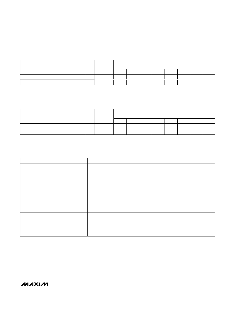
Table 6. Blink Phase 0 Register
REGISTER DATA
REGISTER
R/
W
ADDRESS
CODE
(hex)
D7
D6
D5
D4
D3
D2
D1
D0
Write outputs phase 0
0
Read-back outputs phase 0
1
0x01
OP7
OP6
OP5
OP4
OP3
OP2
OP1
OP0
Table 7. Blink Phase 1 Register
REGISTER DATA
REGISTER
R/
W
ADDRESS
CODE
(hex)
D7
D6
D5
D4
D3
D2
D1
D0
Write outputs phase 1
0
Read-back outputs phase 1
1
0x09
OP7
OP6
OP5
OP4
OP3
OP2
OP1
OP0
Table 8. PWM Application Scenarios
APPLICATION
RECOMMENDED CONFIGURATION
All outputs static without PWM
Set the master, O8 intensity register 0x0E to any value from 0x00 to 0x0F.
The global intensity G bit in the configuration register is don't care.
The output intensity registers 0x10 through 0x13 are don't care.
A mix of static and PWM outputs, with PWM
outputs using different PWM settings
Set the master, O8 intensity register 0x0E to any value from 0x10 to 0xFF.
Clear global intensity G bit to 0 in the configuration register to disable global intensity
control.
For the static outputs, set the output intensity value to 0xF.
For the PWM outputs, set the output intensity value in the range 0x0 to 0xE.
A mix of static and PWM outputs, with PWM
outputs all using the same PWM setting
As above. Global intensity control cannot be used with a mix of static and PWM
outputs, so write the individual intensity registers with the same PWM value.
All outputs PWM using the same PWM
setting
Set the master, O8 intensity register 0x0E to any value from 0x10 to 0xFF.
Set global intensity G bit to 1 in the configuration register to enable global intensity
control.
The master, O8 intensity register 0x0E is the only intensity register used.
The output intensity registers 0x10 through 0x13 are don't care.