Timing characteristics – Rainbow Electronics MAX9729 User Manual
Page 5
MAX9729
Stereo Headphone Amplifier with BassMax,
Volume Control, and Input Mux
_______________________________________________________________________________________
5
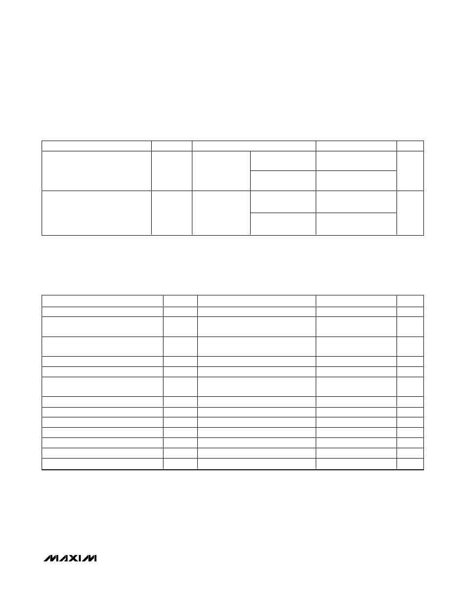
TIMING CHARACTERISTICS
(V
DD
= PV
DD
=
SHDN = 3V, PGND = SGND = 0V, C1 = C2 = C3 = 1µF, BM_ = 0V, maximum gain setting = 6dB, volume setting = -16dB
(overall gain = -10dB), BassMax disabled. Load connected between OUT_ and PGND where specified. T
A
= T
MIN
to T
MAX
, unless other-
wise noted. Typical values are at T
A
= +25°C.) (Notes 1 and 6)
PARAMETER
SYMBOL
CONDITIONS
MIN
TYP
MAX
UNITS
Serial Clock Frequency
f
SCL
0
400
kHz
Bus Free Time Between a STOP and a
START Condition
t
BUF
1.3
µs
Hold Time Repeated for a START
Condition
t
HD:STA
0.6
µs
Low Period of the SCL Clock
t
LOW
1.3
µs
High Period of the SCL Clock
t
HIGH
0.6
µs
Setup Time for a Repeated START
Condition
t
SU:STA
0.6
µs
Data Hold Time
t
HD:DAT
0
0.9
µs
Data Setup Time
t
SU:DAT
100
ns
Rise Time of Both SDA and SCL Signals
t
r
300
ns
Fall Time of Both SDA and SCL Signals
t
f
300
ns
Setup Time for STOP Condition
t
SU:STO
0.6
µs
Pulse Width of Suppressed Spike
t
SP
50
ns
Capacitive Load for Each Bus Line
C
L_BUS
400
pF
ELECTRICAL CHARACTERISTICS (2.4V Supply) (continued)
(V
DD
= PV
DD
=
SHDN = 2.4V, PGND = SGND = 0V, C1 = C2 = C3 = 1µF, BM_ = 0V, maximum gain setting = 6dB, volume attenuation
setting = -16dB (overall gain = -10dB), BassMax disabled. Load connected between OUT_ and PGND where specified. THD+N
measurement BW = 22Hz to 22kHz. T
A
= T
MIN
to T
MAX
, unless otherwise noted. Typical values are at T
A
= +25°C.) (Note 1)
PARAMETER
SYMBOL
CONDITIONS
MIN
TYP
MAX
UNITS
BW = 22Hz to 22kHz
98
Signal-to-Noise Ratio
SNR
R
L
= 32
Ω,
V
OUT
= 1V
RMS
,
overall gain =
3.5dB
BW = 22Hz to 22kHz
and A-weighted
101
dB
Into shutdown
79
Click-and-Pop Level
K
CP
Peak voltage,
A-weighted,
32 samples per
second
(Notes 3 and 5)
Out of shutdown
79
dBV
Note 1: All specifications are 100% tested at T
A
= +25°C. Temperature limits are guaranteed by design.
Note 2: V
DD
and PV
DD
must be connected together.
Note 3: Inputs AC-coupled to SGND.
Note 4: Both channels loaded and driven in phase.
Note 5: Headphone testing performed with a 32Ω resistive load connected to PGND. Mode transitions are controlled by SHDN. K
CP
level is calculated as 20log[(peak voltage during mode transition, no input signal)/1V
RMS
]. Units are expressed in dBV.
Note 6: Guaranteed by design.