Rainbow Electronics MAX9729 User Manual
Page 11
phone, resulting in unnecessary power dissipation and
possible damage to both headphone and headphone
amplifier. In addition to the cost and size disadvan-
tages, the DC-blocking capacitors required by conven-
tional headphone amplifiers limit low-frequency
response and can distort the audio signal.
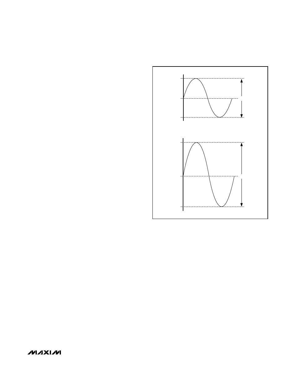
Maxim’s patented DirectDrive architecture uses a
charge pump to create an internal negative supply volt-
age. This allows the MAX9729 headphone amplifier
outputs to be biased about ground, almost doubling
the dynamic range while operating from a single supply
(see Figure 1). With no DC component, there is no
need for the large DC-blocking capacitors. Instead of
two large (up to 220µF) tantalum capacitors, the
MAX9729 charge pump requires only two small 1µF
ceramic capacitors, conserving board space, reducing
cost, and improving the frequency response of the
headphone amplifier. See the Output Power vs.
Charge-Pump Capacitance and Load Resistance
graph in the
Typical Operating Characteristics
for
details of the possible capacitor sizes.
Charge Pump
The MAX9729 features a low-noise charge pump. The
610kHz switching frequency is well beyond the audio
range, and does not interfere with the audio signals.
This enables the MAX9729 to achieve an SNR of 99dB.
The switch drivers feature a controlled switching speed
that minimizes noise generated by turn-on and turn-off
transients. Limiting the switching speed of the charge
pump also minimizes di/dt noise caused by the para-
sitic bond wire and trace inductances.
Click-and-Pop Suppression
In conventional single-supply headphone amplifiers,
the output-coupling capacitor is a major contributor of
audible clicks and pops. The amplifier charges the
coupling capacitor to its output bias voltage at startup.
During shutdown, the capacitor is discharged. The
charging and discharging results in a DC shift across
the capacitor, which appears as an audible transient at
the headphone speaker. Since the MAX9729 head-
phone amplifier does not require output-coupling
capacitors, no audible transients occur.
Additionally, the MAX9729 features extensive click-and-
pop suppression that eliminates any audible transient
sources internal to the device. The Power-Up/Power-
Down Waveform in the
Typical Operating Characteristics
shows that there are minimal transients at the output
upon startup or shutdown.
In most applications, the preamplifier driving the
MAX9729 has a DC bias of typically half the supply.
The input-coupling capacitor is charged to the pream-
plifier’s bias voltage through the MAX9729’s input resis-
tor (R
IN
) during startup. The resulting shift across the
capacitor creates a voltage transient that must settle
before the 50ms turn-on time has elapsed. Delay the
rise of
SHDN by at least 4 time constants (4 x R
IN
x
C
IN
) relative to the start of the preamplifier to avoid
clicks/pops caused by the input filter.
Shutdown
The MAX9729 features a 5µA, low-power shutdown
mode that reduces quiescent current consumption and
extends battery life. Shutdown is controlled by the
SHDN logic input or software interface. Driving the
SHDN input low disables the drive amplifiers, bias cir-
cuitry, charge pump, and sets the headphone amplifier
output resistance to 20kΩ. Similarly, the MAX9729
enters shutdown when bit seven (B7) in the command
register, 0x00, is set to 0 (see the
Command Registers
section).
SHDN and B7 must be high to enable the
MAX9729. The I
2
C/SMBus interface is active and the
MAX9729
Stereo Headphone Amplifier with BassMax,
Volume Control, and Input Mux
______________________________________________________________________________________
11
V
OUT
V
OUT
V
DD
/ 2
GND
V
DD
+V
DD
GND
-V
DD
CONVENTIONAL DRIVER BIASING SCHEME
DirectDrive BIASING SCHEME
V
DD
2V
DD
Figure 1. Traditional Amplifier Output vs. MAX9729 DirectDrive
Output