Max9729, Detailed description, Pin description (continued) – Rainbow Electronics MAX9729 User Manual
Page 10
MAX9729
Detailed Description
The MAX9729 stereo headphone amplifier features
Maxim’s patented DirectDrive architecture, eliminating
the large output-coupling capacitors required by con-
ventional single-supply headphone amplifiers. The
MAX9729 consists of two 52mW Class AB headphone
amplifiers, 3:1 stereo input multiplexer/mixer, two
adjustable gain preamplifiers, a dedicated beep ampli-
fier with independent gain control, hardware/software
shutdown control, inverting charge pump, integrated
32-level volume control, BassMax circuitry, comprehen-
sive click-and-pop suppression circuitry, and an
I
2
C/SMBus-compatible interface (see the
Functional
Diagram/Typical Operating Circuit
). A negative power
supply (PV
SS
) is created internally by inverting the posi-
tive supply (PV
DD
). Powering the amplifiers from V
DD
and PV
SS
increases the dynamic range of the amplifiers
to almost twice that of other single-supply amplifiers,
increasing the total available output power.
An I
2
C/SMBus-compatible interface allows serial com-
munication between the MAX9729 and a microcon-
troller. The MAX9729’s slave address is programmed to
one of two different values using the ADD input allowing
two MAX9729 ICs to share the same bus (see Table 1).
The internal command registers control the shutdown
mode of the MAX9729, select/mix input signal sources,
enable the BassMax circuitry, headphone and beep
amplifier gains, and set the volume level (see Table 2).
The MAX9729’s BassMax circuitry improves audio
reproduction by boosting the bass response of the
amplifier, compensating for any low-frequency attenua-
tion introduced by the headphone. External compo-
nents set the MAX9729’s overall gain allowing for
custom gain settings (see the
BassMax Gain-Setting
Components
section).
DirectDrive
Traditional single-supply headphone amplifiers have
their outputs biased about a nominal DC voltage, typi-
cally half the supply, for maximum dynamic range.
Large coupling capacitors are needed to block this DC
bias from the headphone. Without these capacitors, a
significant amount of DC current flows to the head-
Stereo Headphone Amplifier with BassMax,
Volume Control, and Input Mux
10
______________________________________________________________________________________
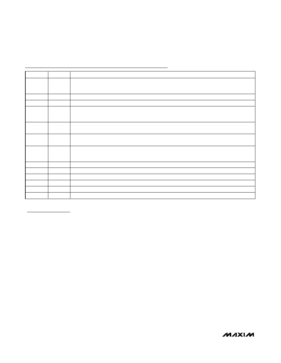
Pin Description (continued)
PIN
NAME
FUNCTION
16
BMR
Right BassMax Input. Connect an external passive network between OUTR and BMR to apply bass
boost to the right-channel output. See the BassMax Gain-Setting Components section. Connect BMR to
SGND if BassMax is not used.
17
OUTR
Right Headphone Output
18
OUTL
Left Headphone Output
19
BML
Left BassMax Input. Connect an external passive network between OUTL and BML to apply bass boost
to the left-channel output. See the BassMax Gain-Setting Components section. Connect BML to SGND,
if BassMax is not used.
20
BEEP_EN
Beep Enable Input. Connect BEEP_EN to PV
DD
to enable the beep amplifier or to PGND to disable the
beep amplifier.
21
SHDN
Active-Low Shutdown Input. Drive SHDN low to disable the MAX9729. Connect SHDN to V
DD
while B7
in command register 0x00 is equal to 1 for normal operation (see Command Registers section).
23
V
DD
Power-Supply Input. Bypass V
DD
to PGND with a 1µF capacitor and connect to PV
DD
. V
DD
and PV
DD
are internally connected and should each have a 1µF bypass capacitor located as to close to the
device as possible.
24
BEEP
Beep Input
25
INL1
Left-Channel Input 1
26
INL2
Left-Channel Input 2
27
INL3
Left-Channel Input 3
28
INR1
Right-Channel Input 1
EP
EP
Exposed Paddle. Connect EP to SV
SS
or leave unconnected.