Read data format, Command registers – Rainbow Electronics MAX9729 User Manual
Page 15
Read Data Format
A read from the MAX9729 includes transmission of a
START condition, the slave address with the R/
W bit
set to 1, one or two bytes of register data sent by the
MAX9729, and a STOP condition. Once the MAX9729
acknowledges the receipt of the slave address and
R/
W bit, the data direction of the SDA line reverses and
the MAX9729 writes the contents of the command reg-
ister 0x00 and 0x01 to the bus in that order. Each byte
sent by the MAX9729 should be acknowledged by the
master device unless the byte is the last data byte of
the transmission, in which case, the master device
should communicate a not acknowledge (NACK). After
the NACK is communicated, the master device termi-
nates the read data transmission by issuing a STOP
condition. Figure 7a illustrates the proper data trans-
mission for reading the contents of register 0x00.
Figure 7b illustrates the proper data transmission for
reading the contents of both registers 0x00 and 0x01 in
a single frame. Data sent by the MAX9729 is valid on
the rising edge of SCL.
When reading register 0x01, register 0x00 must be
read first in the same data frame as shown in Figure 7b.
In other words, when reading register 0x01 both regis-
ters must be read.
Command Registers
The MAX9729 utilizes two command registers to
enable/disable shutdown, control the multiplexer/mixer,
set the volume, set the BEEP input attenuation,
enable/disable BassMax, and set the maximum gain.
Table 2 describes the function of the bits contained in
the command registers.
Set B7 to 0 in register 0x00 to shut down the MAX9729.
The MAX9729 exits shutdown when B7 is set to 1 provid-
ed
SHDN is high. SHDN must be high and B7 must be set
to 1 for the MAX9729 to operate normally (see Table 3).
Bits [6:5] in register 0x00 control the input multiplexer/
mixer. Select the desired input path and enable mixing of
all three stereo input sources with these bits (see Table 4).
Adjust the MAX9729’s volume with bits [4:0] in register
0x00. The volume is adjustable to one of 32 steps rang-
ing from full mute to the maximum gain set by bits
[B2:B0] in register 0x01. Tables 5a, 5b, 5c list all the
possible volume settings and resulting total voltage
MAX9729
Stereo Headphone Amplifier with BassMax,
Volume Control, and Input Mux
______________________________________________________________________________________
15
ACK
0
SLAVE ADDRESS
COMMAND BYTE FOR REGISTER 0x00
B1
B0
B3
B2
B5
B4
B7
B6
ACK
S
P
COMMAND BYTE IS
STORED AFTER ACK
STOP
CONDITION
START
CONDITION
FROM MAX9729
FROM MAX9729
R/W
FROM MASTER DEVICE
FROM MASTER DEVICE
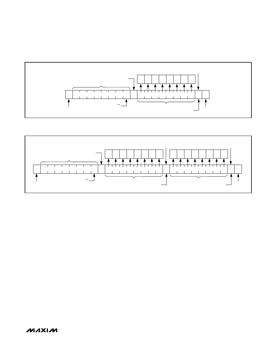
Figure 6a. Write Data Format for Writing to Register 0x00 Only
ACK
0
A
SLAVE ADDRESS
COMMAND BYTE FOR REGISTER 0x01
B1
B0
B3
B2
B5
B4
B7
B6
ACK
S
P
COMMAND BYTE IS
STORED AFTER ACK
STOP
CONDITION
START
CONDITION
FROM MAX9729
FROM MAX9729
R/W
FROM MASTER DEVICE
COMMAND BYTE FOR REGISTER 0x00
B1
B0
B3
B2
B5
B4
B7
B6
COMMAND BYTE IS
STORED AFTER ACK
FROM MAX9729
FROM MASTER DEVICE
FROM MASTER DEVICE
Figure 6b. Write Data Format for Writing to Registers 0x00 and 0x01