Max9729 – Rainbow Electronics MAX9729 User Manual
Page 14
MAX9729
START and STOP Conditions
SDA and SCL idle high when the bus is not in use. A
master device initiates communication by issuing a
START condition. A START condition is a high-to-low
transition on SDA with SCL high. A STOP condition is a
low-to-high transition on SDA while SCL is high (see
Figure 4). A START condition from the master signals
the beginning of a transmission to the MAX9729. The
master terminates transmission, and frees the bus, by
issuing a STOP condition. The bus remains active if a
REPEATED START condition is generated instead of a
STOP condition.
Early STOP Conditions
The MAX9729 recognizes a STOP condition at any
point during data transmission except if the STOP con-
dition occurs in the same high clock pulse as a START
condition. At least one clock pulse must separate any
START and STOP conditions.
Slave Address
The slave address of the MAX9729 is pin programmable
using the ADD input to one of two different values (see
Table 1). The slave address is defined as the 7 most
significant bits (MSBs) of the serial data transmission.
The first byte of information sent to the MAX9729 after
the START condition must contain the slave address
and R/
W bit. R/W bit indicates whether the master is
writing to or reading from the MAX9729 (R/
W = 0 selects
the write condition, R/
W = 1 selects the read condition).
After receiving the proper address, the MAX9729 issues
an ACK by pulling SDA low for one clock cycle.
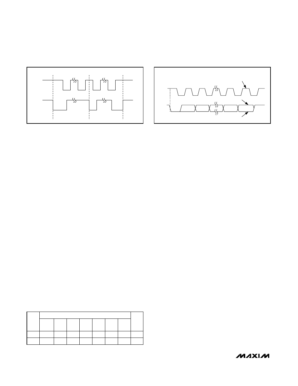
Acknowledge
The acknowledge bit (ACK) is the ninth bit attached to
any byte transmitted over the serial interface (see
Figure 5). ACK is always generated by the receiving
device. The MAX9729 generates an ACK when receiv-
ing a slave address or data by pulling SDA low during
the ninth clock period. The SDA line must remain stable
and low during the high period of the ACK clock pulse.
When transmitting data, the MAX9729 waits for the
receiving device to generate an ACK. Monitoring ACK
allows detection of unsuccessful data transfers. An
unsuccessful data transfer occurs if a receiving device
is busy or if a system fault has occurred. In the event of
an unsuccessful data transfer, the bus master should
reattempt communication at a later time.
Write Data Format
A write to the MAX9729 includes transmission of a
START condition, the slave address with the R/
W bit set
to 0 (see Table 1), one or two command bytes to con-
figure the command registers, and a STOP condition.
Figure 6a illustrates the proper data transmission for
writing to register 0x00 in a single frame. Figure 6b
illustrates the proper data transmission for writing to
both registers 0x00 and 0x01 in a single frame.
As shown in Figures 6a and 6b, the MAX9729 commu-
nicates an ACK after each byte of information is
received. The MAX9729 latches each command byte
into the respective command registers after an ACK is
communicated. The master device terminates the write
data transmission by issuing a STOP condition.
When writing to register 0x01, register 0x00 must be
written to first in the same data frame as shown in
Figure 6b. In other words, when updating register 0x01
both registers must be written to.
Stereo Headphone Amplifier with BassMax,
Volume Control, and Input Mux
14
______________________________________________________________________________________
SCL
SDA
S
Sr
P
Figure 4. START, STOP, and REPEATED START Conditions
1
SCL
START
CONDITION
SDA
2
8
9
CLOCK PULSE FOR
ACKNOWLEDGMENT
ACKNOWLEDGE
NOT ACKNOWLEDGE
Figure 5. Acknowledge
MAX9729 SLAVE ADDRESS
ADD
A6
(MSB)
A5
A4
A3
A2
A1
A0
R/
W
GND
1 0 1 0 0 0 0 0
V
DD
1 0 1 0 0 0 1 0
Table 1. MAX9729 Slave Address with
R/W Bit