Table 6. beep level (register 0x01), Table 7. bassmax control (register 0x01) – Rainbow Electronics MAX9729 User Manual
Page 21
Charge-Pump Flying Capacitor (C1)
The charge-pump flying capacitor connected between
C1N and C1P affects the charge pump’s load regula-
tion and output impedance. Choosing too small a flying
capacitor degrades the MAX9729’s ability to provide
sufficient current drive and leads to a loss of output
voltage. Increasing the value of the flying capacitor
improves load regulation and reduces the charge-
pump output impedance. See the Output Power vs.
Charge-Pump Capacitance and Load Resistance
graph in the
Typical Operating Characteristics
. Place
C1 physically close to C1P and C1N. Use a 1µF capac-
itor for C1 in most applications.
Charge-Pump Hold Capacitor (C2)
The hold capacitor’s value and ESR directly affect the
ripple at PV
SS
. Ripple is reduced by increasing the
value of the hold capacitor. Choosing a capacitor with
lower ESR reduces ripple and output impedance. Lower
capacitance values can be used in systems with low
maximum output power levels. See the Output Power vs.
Charge-Pump Capacitance and Load Resistance graph
in the
Typical Operating Characteristics
. C2 should be
equal to the value of C1. Place C2 physically close to
PV
SS
and SV
SS
. Connect PV
SS
and SV
SS
together at
C2. Use a 1µF capacitor for C2 in most applications.
PV
DD
Bypass Capacitor (C3)
The PV
DD
bypass capacitor lowers the output imped-
ance of the power supply and reduces the impact of
the MAX9729’s charge-pump switching transients. C3
should be greater than or equal to C1. Place C3 physi-
cally close to PV
DD
.
MAX9729
Stereo Headphone Amplifier with BassMax,
Volume Control, and Input Mux
______________________________________________________________________________________
21
100
70
80
90
50
60
10
20
30
40
0
0
5
10
15
20
25
30
35
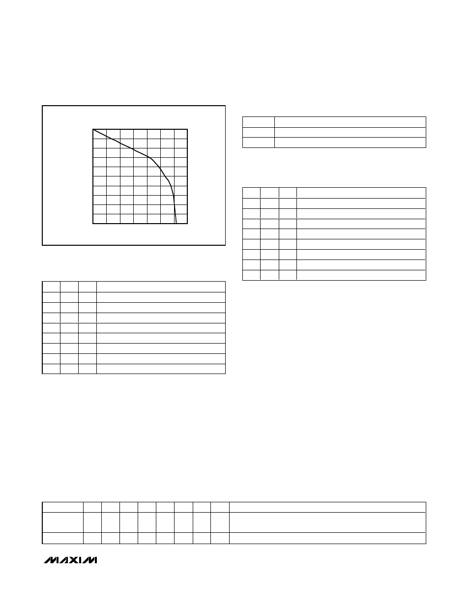
MAX9729 VOLUME CONTROL
TRANSFER FUNCTION
CODE (DECIMAL)
ATTENUATION (dB)
Figure 8. MAX9729 Volume Control Transfer Function
B7
B6
B5
BEEP LEVEL (dBV)
0
0
0
-10
0
0
1
-20
0
1
0
-30
0
1
1
-40
1
0
0
-50
1
0
1
-52
1
1
0
-54
1
1
1
-56
Table 6. Beep Level (Register 0x01)
BEEP level referenced to a 3V BEEP input.
B3
MODE
0
BassMax Disabled
1
BassMax Enabled
Table 7. BassMax Control (Register 0x01)
B2
B1
B0
MAXIMUM GAIN (dB)
0
0
0
3.5
0
0
1
6
0
1
0
8
0
1
1
10
1
0
0
19.5
1
0
1
22
1
1
0
24
1
1
1
26
Table 8. Maximum Gain Control
(Register 0x01)
Table 9. Initial Power-Up Command Register Status
REGISTER
B7
B6
B5
B4
B3
B2
B1
B0
POR SETTINGS
0x00
1
0
0
0
1
0
1
1
Shutdown mode disabled (assuming V
SHDN
= V
DD
), INL1 and
INR1 inputs selected, ATTEN = 16dB (A
V_TOTAL
= -10dB)
0x01
1
1
1
1
1
0
0
1
Beep input attenuation = 56dB, BassMax enabled, A
V_MAX
= 6dB