Package dimensions, Pin p-dip, Pin so wide body – Rainbow Electronics W27E010 User Manual
Page 13
W27E010
Publication Release Date: May 1997
- 13 -
Revision A5
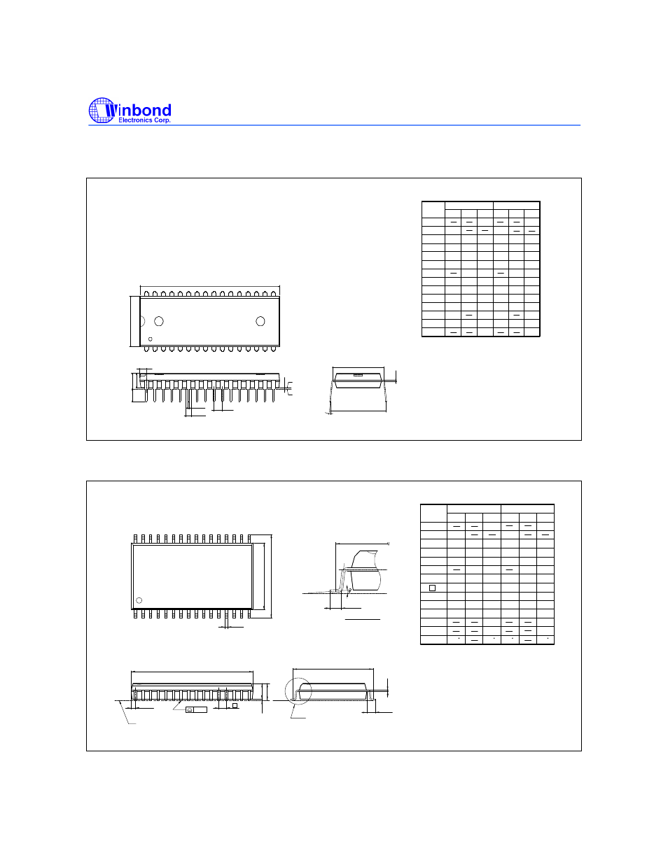
PACKAGE DIMENSIONS
32-pin P-DIP
Seating Plane
e
A
2
A
a
c
E
Base Plane
1
A
1
e
L
A
S
1
E
D
1
B
B
32
1
16
17
1. Dimensions D Max. & S include mold flash or
tie bar burrs.
2. Dimension E1 does not include interlead flash.
3. Dimensions D & E1 include mold mismatch and
are determined at the mold parting line.
6. General appearance spec. should be based on
final visual inspection spec.
Notes:
4. Dimension B1 does not include dambar
protrusion/intrusion.
5. Controlling dimension: Inches.
1.37
1.22
0.054
0.048
Symbol
Min. Nom. Max.
Max.
Nom.
Min.
Dimension in Inches Dimension in mm
A
B
c
D
e
A
L
S
A
A
1
2
E
0.050
1.27
0.210
5.33
0.010
0.150
0.016
0.155
0.018
0.160
0.022
3.81
0.41
0.25
3.94
0.46
4.06
0.56
0.008
0.120
0.670
0.010
0.130
0.014
0.140
0.20
3.05
0.25
3.30
0.36
3.56
0.540
0.555
0.550
13.84
14.10
13.97
17.02
15.24
14.99
15.49
0.600
0.590
0.610
2.29
2.54
2.79
0.090
0.100
0.110
B
1
1
e
E
1
a
1.650
1.660
41.91
42.16
0
15
0.085
2.16
0.650
0.630
16.00
16.51
15
0
32-pin SO Wide Body
1
17
32
16
y
e
D
S
Seating Plane
b
A
A
E H
L
L
E
E
1
c
e
1
1
e
A
2
See Detail F
Detail F
1. Dimensions D Max. & S include mold flash
or tie bar burrs.
2. Dimension b does not include dambar
protrusion/intrusion.
3. Dimensions D & E include mold mismatch
and are determined at the mold parting line.
.
Notes:
4. Controlling dimension: Inches.
5. General appearance spec should be based
on final visual inspection spec.
Symbol
Min. Nom. Max.
Max.
Nom.
Min.
Dimension in Inches
Dimension in mm
A
b
c
D
e
H
E
L
y
A
A
L
E
1
2
E
0.118
3.00
0
10
10
0
S
0.20
0.15
0.008
0.006
0.012
0.31
0.004
0.101
0.014
0.106
0.016
0.111
0.020
2.57
0.36
0.10
2.69
0.41
2.82
0.51
0.047
0.004
0.805
0.055
0.817
0.063
1.19
20.45
1.40
20.75
1.60
0.556
0.556
0.546
14.38
14.12
13.87
0.10
11.43
11.30
11.18
0.450
0.445
0.440
0.58
0.79
0.99
0.023
0.031
0.039
1.12
1.27
1.42
0.044
0.050
0.056
0.91
0.036
θ