Installation and setup, Overview, Setting card jumpers – Cobalt Digital COMPASS 9363 Multi-Format Reference Generator User Manual
Page 19: Chapter 2, R 2, “installation and setup
9363-OM (V1.2)
9363 PRODUCT MANUAL
2-1
Chapter 2
Chapter 2
Installation and Setup
Overview
This chapter contains the following information:
•
•
Installing the 9363 Into a Frame Slot (p. 2-4)
•
Installing a Rear I/O Module (p. 2-2)
•
Setting Up 9363 Network Remote Control (p. 2-5)
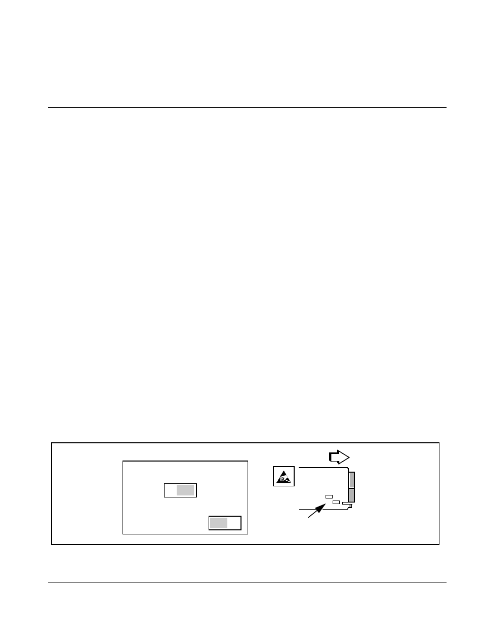
Setting Card Jumpers
The
AUX I/O
connector on the 9363 Rear I/O Module is a multi-purpose BNC
port that can be set as either a
Local (External)
BNC reference source input,
or an AES/Word Clock (
AES/WC OUT
) output depending on the jumper
positions.
(See Figure 2-1.) Jumpers
JP1
and
JP2
set the
AUX I/O
BNC connector
function as described below. Depending on function desired, set these jumpers
before installing the card in a frame.
• JP1 (EXT TERM) – Sets card aux BNC connector to use card internal
75-ohm termination. This position is the default position and is recom-
mended unless the connection is to be looped within a 75-ohm externally
terminated chain.
• JP2 (REF IN / AES OUT) – Sets card aux BNC connector to either serve as
an extra (Local/External) reference input (factory default position), or serve
as an AES/word clock output (AES/WC OUT).
Figure 2-1 9363 Termination and AUX I/O BNC Jumpers
Rear of Card
• • •
JP1 (Ext Ref)
OFF ON
• • •
JP2
REF AES
IN OUT
Note: Default factory settings shown.