Turbosmart FUEL CUT DEFENDERS - FCD2 (electronic) User Manual
Page 3
3
SETTING EXAMPLES
These setting examples are to aid in understanding the various settings of the FCD2 and should not be used as a tuning guide.
IMPORTANT! See following instructions for tuning your FCD2.
For most vehicles the setup is quite simple. On a dyno, bring the engine onto full boost until the factory boost cut is activated, taking
note of the boost level at which this occurs. Then turn the clamp adjustment dial on the front of the FCD2 ANTI-CLOCKWISE until the
indicator light just illuminates. The GREEN LED indicator light should turn on just before the factory boost cut point. Activating the boost
cut defender any earlier than this could cause the engine to run “LEAN” resulting in possible engine damage.
With the clamping level set the release voltage or new cut point can be set. When the release dial is set to 10 the unit will release when
the sensor signal reaches 5.5V. If you know the boost level that you want the fuel cut to return with the aid of an assistant, drive the
vehicle bringing the engine onto full boost at the maximum boost level you want to run before fuel cut. Then adjust the release dial anti-
clockwise until the RED LED illuminates and vehicle begins to fuel cut. This dial should be set just above the maximum boost level you
require. Check the A/F ratio once the FCD2 has been set.
------------------------------------------------------------------------------------------------------------------------
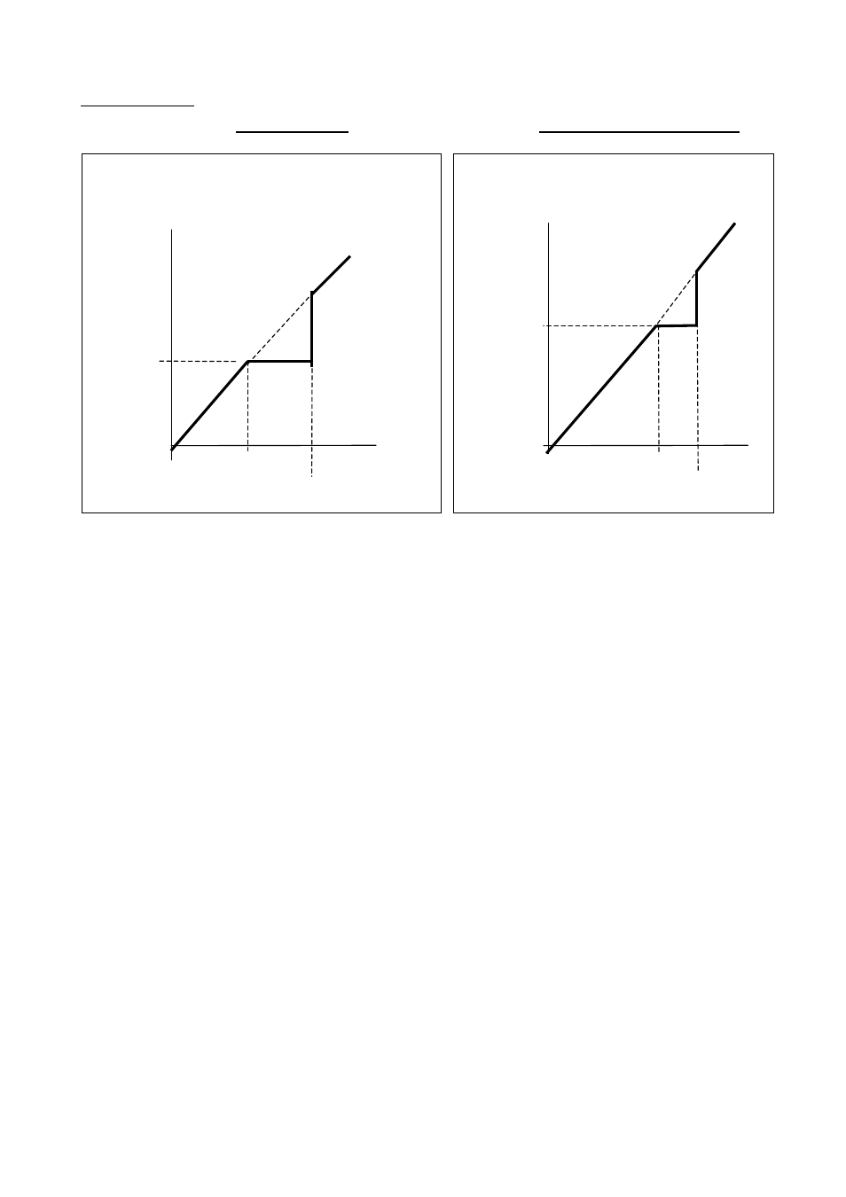
Voltage
From
Sensor
Voltage from sensor into FCD vs. output voltage from FCD to
ECU for settings: CLAMP: 1, RELEASE: 6
Voltage to
ECU
“CLAMP”
Voltage
(3V)
@ Setting 1
“RELEASE” voltage 4.4V @
Setting 6
Voltage
From Sensor
Voltage from sensor into FCD vs. output voltage from
FCD to ECU for settings: CLAMP: 5, RELEASE: 8
Voltage to
ECU
“RELEASE” voltage 4.9V @
Setting 8
“CLAMP”
Voltage (4.1V)
@ Setting 5