How to install your fuel cut defender cont, Tuning your fuel cut defender – Turbosmart FUEL CUT DEFENDERS - FCD2 (electronic) User Manual
Page 2
2
HOW TO INSTALL YOUR FUEL CUT DEFENDER cont.
The output wire of your MAP sensor or AFM can be easily located using a digital multimeter or consulting your service manual if not
listed. When using a digital multimeter ensure the meter is set to read voltage in the 0-10V range. Place the negative probe of your
multimeter on the vehicles chassis and with the car idling, slowly rev the engine. With the positive probe you should be able to read a
change in output on one of the wires connected to the MAP sensor or AFM with increasing rpm. Alternatively with ignition switched and
engine off, blow air through the AFM or apply pressure to the MAP sensor using a vacuum/pressure source. This should also give a
change in voltage on the sensor output wire. Once you have identified the correct wire the wire should be cut and the input and output
of the FCD2 should be connected to the wires as shown in the above diagram.
WIRING:
Mount the FCD2 in a suitable location within the cabin using the supplied screws.
------------------------------------------------------------------------------------------------------------------------
TUNING YOUR FUEL CUT DEFENDER
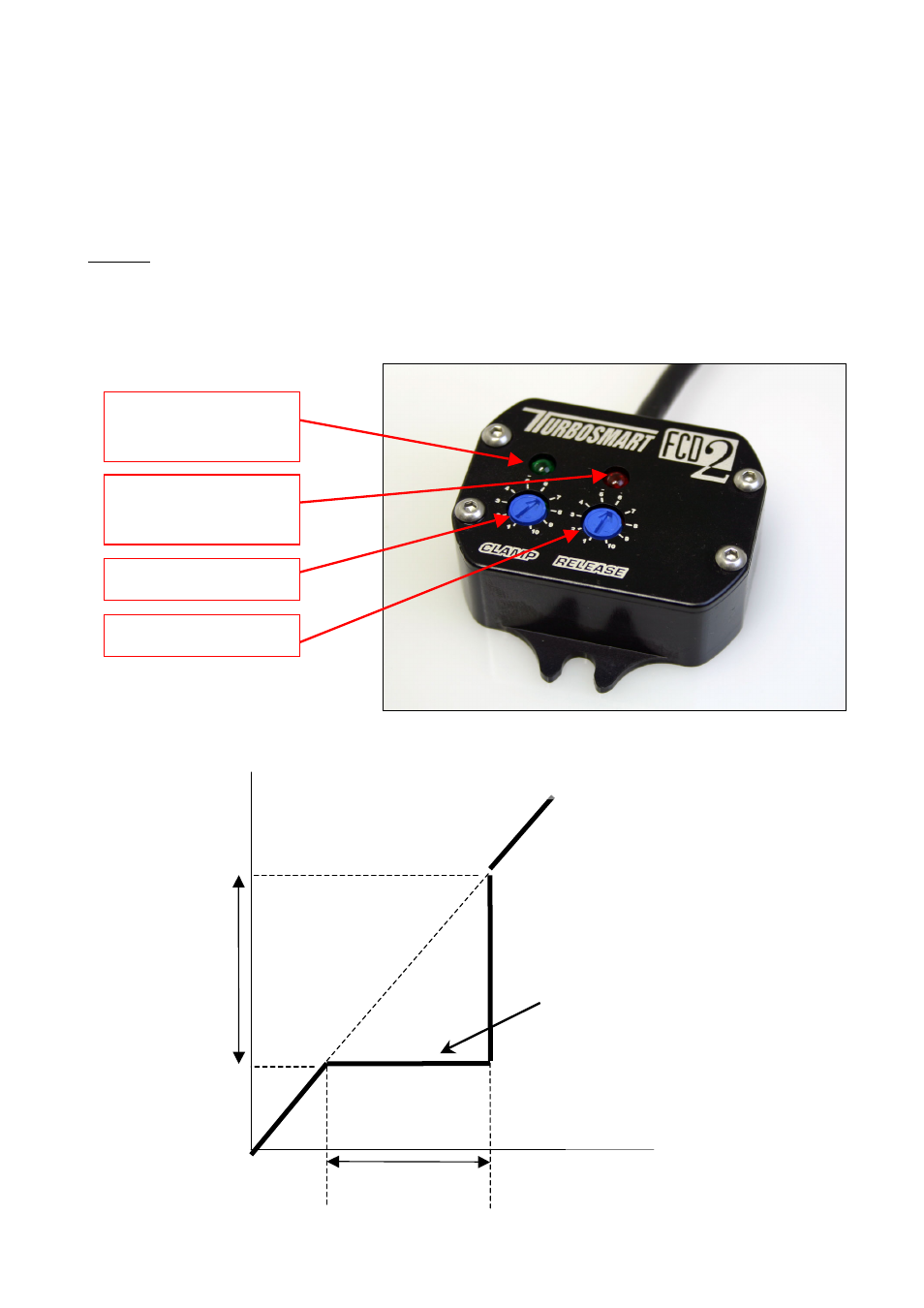
This view shows the two adjustments on the FCD2.
The Graph below illustrates the effect of each adjustment dial on the sensor output.
Green Indicator LED to show
when unit is clamping voltage
signal
Red Indicator LED to show
when unit has released voltage
signal
Voltage
From Sensor
Voltage to
ECU
Adjustable
“CLAMP”
Voltage
“RELEASE” clamping
voltage adjustment
CLAMP Setting 1 = 3V
RELEASE Setting 1 = CLAMP Voltage
RELEASE Setting 10 = 5.5V
CLAMP Setting 10 = 5.5V
Voltage from sensor into FCD vs. output voltage from FCD to ECU
Clamp voltage
level
CLAMP DIAL
RELEASE DIAL