Electronics LP2000_VAR User Manual
Page 9
9
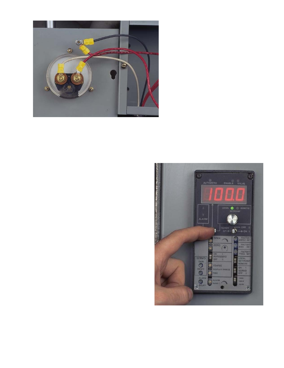
Fig. 16 Apply control power circuit.
Caution: be sure all wiring has been
properly completed and that no shock
hazard exists. The AC controller is factory
set to display 100.0 Amps full scale when
connected to a 100:5 ratio current trans-
former. The display range can be verified
by pressing Coarse Display Range.
Fig. 15
Fig. 15 Attach the loose current trans-
former wire to one of the AC controller
shunt wires and attach the other AC
controller shunt wire to the meter lug.
This procedure allows the AC controller
shunt to be in series with the existing
panel meter so that both of them re-
ceive the (transformed) motor current
(0-5 Amps). If the panel meter is to be
eliminated then connect the two current
transformer output wires directly to the
AC controller shunt.
Fig. 16
- Pot-24 (2 pages)
- WM 3000-24 (2 pages)
- WM 3000-24 (10 pages)
- 500-P (10 pages)
- 500-P (2 pages)
- LP2000VAR (2 pages)
- FC (2 pages)
- FC (21 pages)
- LP2000_VAR (2 pages)
- VLP1000_VAR (2 pages)
- LP-24 (2 pages)
- LP-24 (15 pages)
- 576-24 (2 pages)
- AC (2 pages)
- AC (25 pages)
- 578-24 (2 pages)
- 590 (8 pages)
- 590 (2 pages)
- 590-24 (2 pages)
- 590-24 (26 pages)
- 577 (2 pages)
- FC-24 (2 pages)
- FC-24 (12 pages)
- 190-AC (2 pages)
- 100 (2 pages)
- VLP-24 (2 pages)
- 0-120 Vac Variac (1 page)
- AC-24 (16 pages)
- AC-24 (2 pages)
- MC (12 pages)
- MC (2 pages)
- 179-AC (2 pages)
- VLP1000 (2 pages)
- 580-24 (2 pages)
- 178-DC (2 pages)
- 577-24 (2 pages)
- 500-24 (6 pages)
- 500-24 (2 pages)
- 180-AC (2 pages)
- LP2000 (2 pages)
- VLP1000VAR (2 pages)