Electronics LP2000_VAR User Manual
Page 7
7
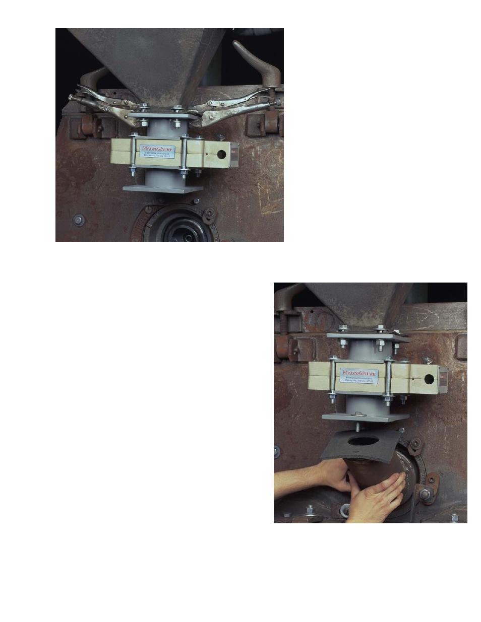
Fig. 10 The adapter plates should be
preinstalled onto the MagnaValve and
the assembly installed as a single unit,
The entire MagnaValve assembly can
be temporarily positioned and held into
place by using vise-grip or similar pli-
ers and then the bolts can be installed
and tightened.
Fig. 11 The feed spout can now be rein-
stalled easily, since it bolts directly to the
special adapter plate. Be sure to use a
rubber gasket between the adaptor plate
and the feed spout. Do not use silicon rub-
ber or any other adhesive that will make it
difficult to remove the valve for inspection.
Fig. 10
Fig. 11
Note:Adding a nonmetallic 1” spacer
above and below the Magnavalve will
significantly improve MagnaValve per-
formance.
See also other documents in the category Electronics Relay:
- Pot-24 (2 pages)
- WM 3000-24 (2 pages)
- WM 3000-24 (10 pages)
- 500-P (10 pages)
- 500-P (2 pages)
- LP2000VAR (2 pages)
- FC (2 pages)
- FC (21 pages)
- LP2000_VAR (2 pages)
- VLP1000_VAR (2 pages)
- LP-24 (2 pages)
- LP-24 (15 pages)
- 576-24 (2 pages)
- AC (2 pages)
- AC (25 pages)
- 578-24 (2 pages)
- 590 (8 pages)
- 590 (2 pages)
- 590-24 (2 pages)
- 590-24 (26 pages)
- 577 (2 pages)
- FC-24 (2 pages)
- FC-24 (12 pages)
- 190-AC (2 pages)
- 100 (2 pages)
- VLP-24 (2 pages)
- 0-120 Vac Variac (1 page)
- AC-24 (16 pages)
- AC-24 (2 pages)
- MC (12 pages)
- MC (2 pages)
- 179-AC (2 pages)
- VLP1000 (2 pages)
- 580-24 (2 pages)
- 178-DC (2 pages)
- 577-24 (2 pages)
- 500-24 (6 pages)
- 500-24 (2 pages)
- 180-AC (2 pages)
- LP2000 (2 pages)
- VLP1000VAR (2 pages)