Chapter 2: installation guidelines – Grain Systems PNEG-1891 User Manual
Page 13
Chapter 2: Installation Guidelines
To prevent the dryer from overturning or moving laterally, the dryer must be secured to the foundation
using anchor bolts or cables. Anchor bolts can be cast into the concrete slab and secured to the dryer
legs. The dryer can also be secured using cables and turnbuckles that are fastened to the anchors that are
installed at the edge of the concrete slab.
Table 2-1 General reference for concrete materials needed for each size dryer foundation.
Dryer basket length
8
12
14
16
18
20
22
26
Concrete pad size (ft x ft)
12 x 18
12 x 22
12 x 24
12 x 26
12 x 28
12 x 30
12 x 32
12 x 36
Concrete pad size (m x m)
3.7 x 5.5
3.7 x 6.7
3.7 x 7.3
3.7 x 7.9 3.7 x 8.5 3.7 x 9.1
3.7 x 9.8
3.7 x 11
Concrete yards (meters)
5.9 (5.4)
7.1 (6.5)
7.7 (7.0)
8.3 (7.6) 8.9 (8.1) 9.2 (8.4) 10.1 (9.2)
11.3
(10.3)
Quantity of reinforcing rods
20 in. (50.8 cm) each
6
7
7
8
8
8
9
10
Wire mesh sq—ft (sq m )
20.0
(216)
24.5
(264)
26.7
(288)
29.0
(312)
31.2
(336)
33.4
(360)
35.7
(384)
40.1
(432)
Steel legs (minimum
quantity)
8
10
12
12
14
14
16
18
Anchors
4
6
6
6
8
8
8
10
Blocks
14
18
18
18
22
22
26
30
Feet (Meters) of 2 x 6
boards
14 (4.3)
18 (5.5)
18 (5.5)
18 (5.5)
22 (6.7)
22 (6.7)
26 (7.9)
30 (9.1)
Quantity of turnbuckles
4
6
6
6
8
8
8
10
Estimated man-hours
10
14
18
18
20
22
24
28
Quantities are approximate and requirements might vary due to site elevations.
Setup times do not include site preparations and the pouring of the concrete pad.
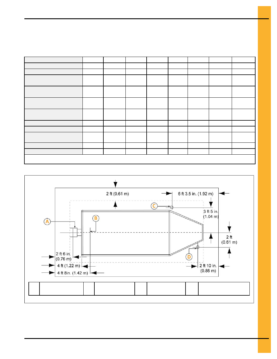
Figure 2-3 Recommended locations for external equipment
A
Grain discharge
area
B
Fill-hopper
C
Gas pipe
location
D
Electrical service
location
Pneg-1891 Portable Dryers
13