Nt. see, Dryer start-up – Grain Systems PNEG-1797 User Manual
Page 44
7. Dryer Start-Up
44
PNEG-1797CE CE Approved T-Series Tower Dryer
7. Checking pilot flame current.
a. The minimum flame signal, measured at the burner control, should be 1.25 VDC.
b. Flame signal can be checked at the Honeywell burner control, located in the main power panel,
as shown in
.
c. Flame rod may be re-positioned or gently bent to get better contact with the flame. Ensure rod is
well clear of burner to prevent grounding when hot. Be careful not to damage ceramic insulator
surrounding flame rod.
d. Check burner is properly grounded.
e. Check neutral supply to burner control is 0 VAC.
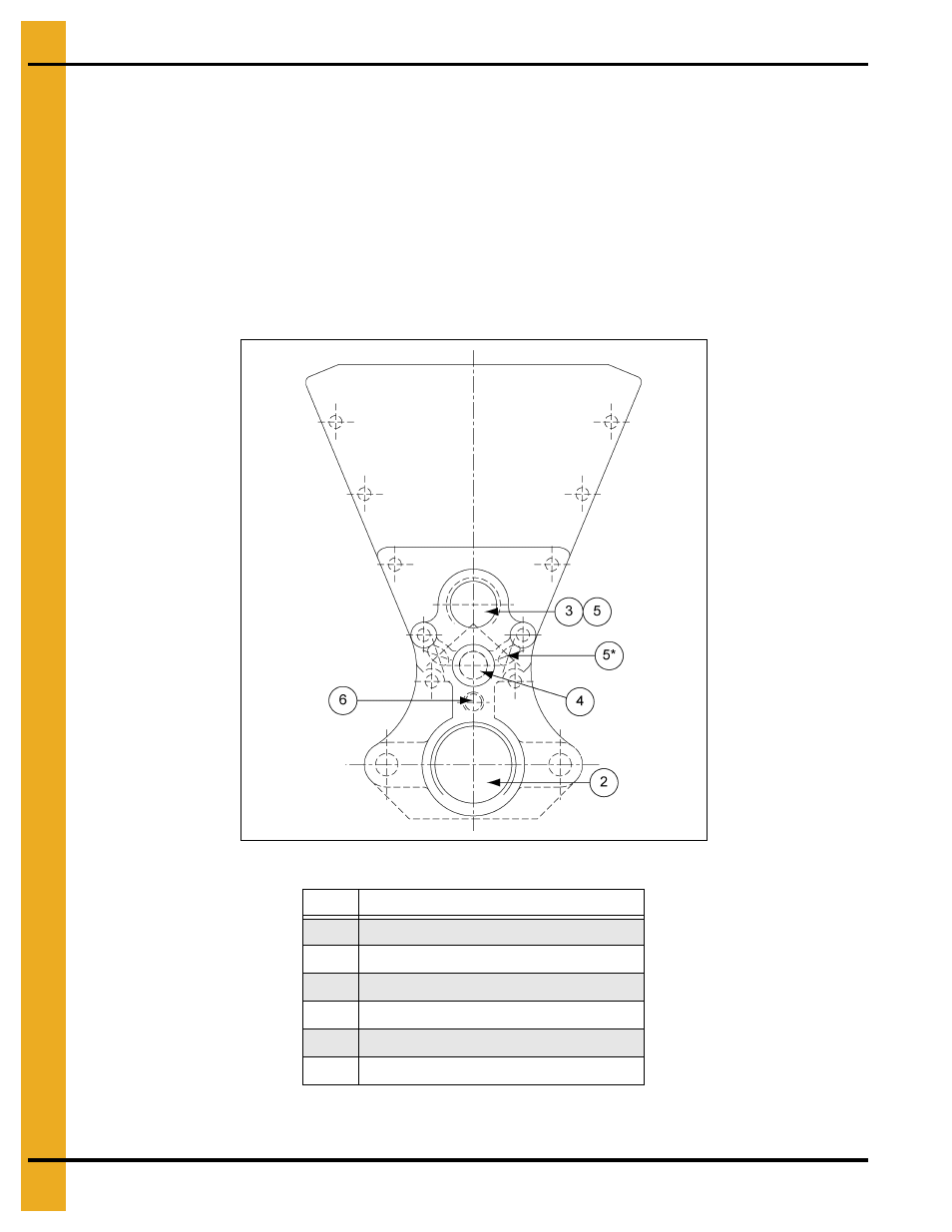
Figure 7B Burner End Plate, Spark, Pilot and Flame Rod Locations
NOTE: Minimum acceptable flame signal is 1.25 VDC.
Ref #
Description
2
Main Gas
3
UV Sensor Connection (Optional)
4
Spark Ignitor
5
Flame Rod Locations
5*
Flame Rod Alternate Locations
6
Pilot Gas
- PNEG-1890 (16 pages)
- PNEG-595 (26 pages)
- PNEG-1472 (30 pages)
- PNEG-897 (58 pages)
- PNEG-838 (4 pages)
- PNEG-1755 (36 pages)
- PNEG-524 (24 pages)
- PNEG-1080 (2 pages)
- PNEG-728 (47 pages)
- PNEG-673 (57 pages)
- PNEG-1717 (88 pages)
- PNEG-823 (42 pages)
- PNEG-630-6S (23 pages)
- PNEG-1876 (80 pages)
- PNEG-102 (2 pages)
- PNEG-366 (51 pages)
- PNEG-1626 (1 page)
- PNEG-1874 (78 pages)
- PNEG-1798 (34 pages)
- PNEG-1927 (4 pages)
- PNEG-924 (2 pages)
- PNEG-582 (26 pages)
- PNEG-012 (46 pages)
- PNEG-546 (26 pages)
- PNEG-951 (102 pages)
- PNEG-1650 (92 pages)
- PNEG-1649 (50 pages)
- PNEG-1376 (88 pages)
- PNEG-361 (46 pages)
- PNEG-338 (32 pages)
- PNEG-1276 (78 pages)
- PNEG-1283 (22 pages)
- PNEG-1089 (14 pages)
- QSG-001 (2 pages)
- PNEG-950 (96 pages)
- PNEG-1590 (3 pages)
- PNEG-501 (33 pages)
- PNEG-1447 (68 pages)
- PNEG-707GSI (446 pages)
- PNEG-349 (32 pages)
- PNEG-236 (22 pages)
- PNEG-743 (16 pages)
- PNEG-900 (54 pages)
- PNEG-1935 (92 pages)