Banks Power Dodge Trucks: (Diesel ’03 - 07 5.9L Cummins) PowerPack & Stinger w_EconoMind '03-05 For use with PowerPDA User Manual
Page 8
1.
Disconnect the battery ground
cables from each of the batteries.
Secure the cables so that they do
not come in contact with the battery
posts during the installation.
2.
Raise the vehicle and support it
with properly weight rated safety
stands, ramps or a commercial hoist.
Follow the manufacturer’s safety
precautions. Take care to balance
the vehicle to prevent it from slipping
or falling. When using ramps, be
sure the front wheels are centered
squarely on the topsides; place the
transmission in park; set the parking
brake and place blocks behind the
rear wheels.
CAuTIoN: Do NoT WoRK uNDER
ANy VEHIClE SuPPoRTED oNly
By A JACK. SEVERE INJuRy MAy
RESulT.
WARNING! The following step
requires the use of a torch and/or
saw. Proper safety equipment
should be used. Failure to use
proper safety equipment may
result in severe injury.
3.
From under the vehicle remove
the factory exhaust system. Starting
at the rear of the vehicle, remove tail
pipe, muffler and any extension pipes
attached to the outlet of the catalytic
converter, by either cutting through
the pipe near the clamps or by
removing the clamps and heating the
joints with an oxy-acetylene torch to
allow crimped pipes to separate.Do
NoT CuT oR DAMAGE CATAlyTIC
CoNVERTER TuBING DuRING THE
REMoVAl PRoCESS. Remove the
hanger pins from the rubber hangers
with a pry bar. (Spray lubricant will
ease hanger removal.)
Steps 4 thru 10 for 2003-2004
Step 11 for 2005
4.
Remove the clamp attaching
the turbine outlet pipe (T.O.P) to
the catalytic converter headpipe
(or intermediate pipe if applicable)
and remove the catalytic converter
assembly or intermediate pipe.
5.
Remove the V-band clamp that
attaches the turbine outlet elbow to
the turbine housing and remove the
turbine outlet pipe and elbow from
the vehicle.
6.
Attach the supplied T.O.P. gasket
to the Banks T.O.P. Loosely place
the supplied V-band clamp on the
Banks T.O.P. Install the Banks T.O.P.
to the turbine housing (note: the
factory turbine outlet elbow will not
be used). Loosely snug the V-band
clamp assuring the gasket and T.O.P
are aligned properly.
7.
For vehicles that are NOT
equipped with a catalytic converter,
install the supplied Banks front
intermediate pipe and supplied
gasket onto the previously installed
Banks T.O.P. Place a small amount
of anti-seize onto the four (4)
7
⁄
16
”
bolts. Loosely install the supplied
7
⁄
16
” hardware onto the T.O.P. and
intermediate pipe flange (see Figure
1). Proceed to Step 10.
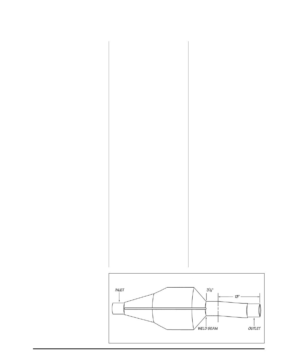
8.
For vehicles equipped with
catalytic converters: With the
catalytic converter removed from the
vehicle and the headpipe removed
from the converter, measure 13”
inward from the outlet tubing rim
(3-
1
⁄
2
” of tubing from the outlet weld
should remain). Using a reciprocating
saw or equivalent, vertically cut and
remove 13” from the converter outlet
tubing (see Figure 2).
9.
Install the supplied 3-
1
⁄
2
” clamp
onto the catalytic converter inlet.
Place the catalytic converter onto
the previously installed intermediate
pipe. Loosely snug the clamp on the
catalytic converter inlet.
IMPoRTANT: If the vehicle
is equipped with a catalytic
converter, it should be inspected.
Diesel catalysts may become
plugged with soot and can
cause a restriction to exhaust
flow, impeding performance.
Shine a powerful flashlight into
the inlet end of the converter.
observe the light through the
other end of the converter. The
full circle of the flashlight should
be visible without any blockage
in the gridwork of the catalyst.
If excessive soot is observed,
the catalyst may need to be
cleaned. TAKE PRECAuTIoNS
to avoid blowing soot toward
the work area or where it
could be inhaled. AlWAyS
use breathing protection. Also
inspect the catalyst for damage
(i.e. chips, bent corners, etc.) to
the gridwork. If your catalytic
converter is damaged, it may
be covered under your vehicle’s
emissions warranty.
10.
Place a supplied 4” clamp
onto the front of the supplied
rear intermediate pipe. Install the
intermediate pipe onto the catalytic
converter outlet or the front
intermediate pipe. Lightly snug the
exhaust clamp near the rim of the
intermediate pipe.
11.
2005 NOTE: The catalytic
converter will not be removed
from the vehicle. Remove attached
intermediate pipe and corresponding
clamp(s). Take care not to damage
the catalytic converter outlet end.
Step 12 thru 20 for Single Tip
Step 21 thru 33 for Split Dual
12.
2003-2004 For quad cab long
bed (160.5” wheelbase) models only:
Place a supplied 4” clamp onto the
front of the supplied extension pipe.
Install the extension pipe hanger
pin into the corresponding rubber
hanger. Connect the extension pipe
onto the intermediate pipe and
loosely snug the 4” clamp.
13.
For Crew Cab Long Bed (160.5”
wheelbase) ONLY, install a 4”
exhaust clamp onto the front of
the Banks intermediate pipe. Install
the intermediate pipe onto the
catalytic converter outlet. Install the
intermediate pipe hanger onto the
corresponding rubber hanger. Loosely
snug the 4” clamp.
Figure 2
8
96812 v.7.0