Rough Country 376.20 User Manual
Page 5
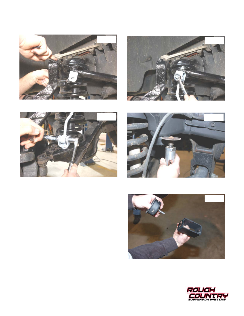
28. Install the sway bar bracket on the sway bar with the supplied 12mm x 35mm bolt and flange lock nut. See Photo
19.
29. Install the link in the upper and lower brackets and secure with 12mm x 65mm bolts and flange lock nuts. See Photo
20 & 21. Tighten the upper and lower brackets and links using a 18mm & 19mm socket / wrench.
30. Remove the rubber bump stop from the bump stop cup and remove the mounting cup from the frame using a cutting
wheel as shown in Photo 22.
31. Reinstall the stock bump stop cup on the bump stop bracket as shown in Photo 23 using the supplied 3/8” x 1 1/4”
bolts, washers/nuts.
32. Reinstall the bracket in the stock location on the frame us-
ing the supplied 3/8” 1 1/4” bolts, washers & flange lock
nuts . Reinstall the stock rubber bump stop in the bump
stop cup.
33. Locate shock part number 8117 hydraulic shock/ 9117 ni-
trogen charged shock. Using the stock bolts and a 13mm
socket bolt the bottom of the shocks into the factory loca-
tion. Install provided bushings on the top of the shock and
tighten using a 18mm wrench. Do not over tighten, only
buldge the bushings.
34. Using a 7/8” socket reinstall tires and wheels.
35. Jack up the front of the vehicle and remove the jack
stands. Lower the vehicle to the floor.
36. Using a 21mm wrench and a 24mm socket tighten the and
lower control arms to factory specs. Using a 24mm wrench
and 24mm socket tighten the cross member to factory
specs.
Photo 22
Photo 23
Photo 19
Photo 20
Photo 21