Rough Country 376.20 User Manual
Page 4
20. Install new Rough Country coil spring part # 9293, be sure that the factory rubber isolator is still in place on the top
of the coil seat. Rotate coil until it is properly seated.
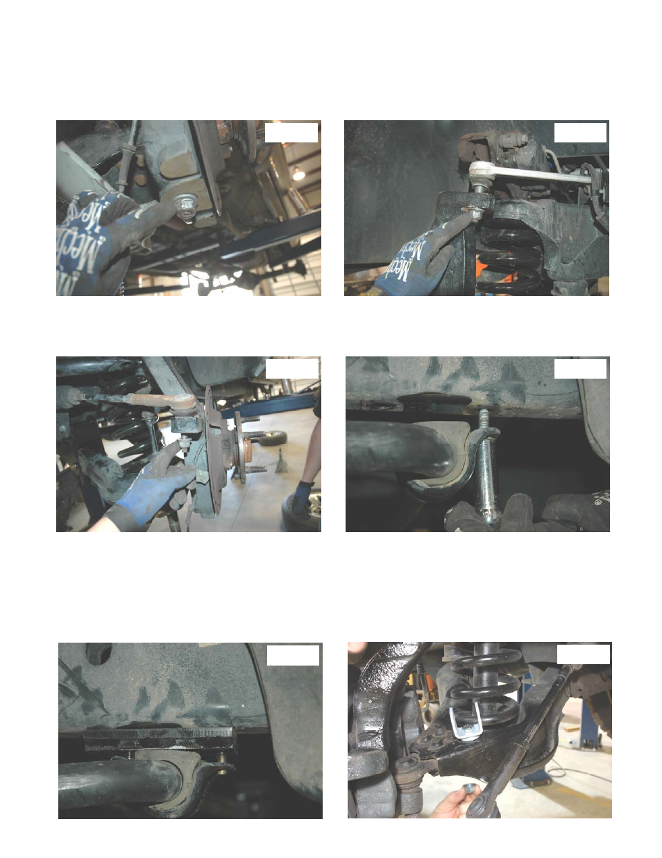
21. Place a jack stand under the lower control arm. Reinstall the new spindle on the lower control arm ball joint and in-
stall the factory nut. Torque to factory specs. See Photo 13.
22. Push the spindle up to reinstall the upper control arm ball joint. Reinstall the factory nut, torque to factory specs. See
Photo 14.
23. Reinstall rack–pinion tie rod end on the spindle. Reinstall the factory nut, torque to factory specs. See Photo 15. Re-
install ABS wires from step 5 and 6. Repeat steps 19-23 on opposite side.
24. Using a 15mm socket remover the factory sway bar bracket from the frame as shown in Photo 16. Keep factory
bolts for the next step.
25. Locate sway bar bracket from 1376BOX3. Insert the (2) 3/8” x 1.25” bolts provided in the kit bag into the bracket with
the hex holes. Bolt the sway bar drop bracket in the stock location using the stock bolts from the last step. Torque to
factory specs.
26. Align the bolts from the sway bar drop bracket with the holes in the factory bar. Using the supplied washers and
nuts, tighten using a 14mm socket. Torque to factory specs. See Photo 17.
27. Locate the new sway bar link bracket and install as shown in Photo 18 on the lower control arm with the supplied
12mm x 50mm bolt, flange lock nut and thick washer under the bracket. Do not tighten at this time. Repeat on oppo-
site side.
Photo 13
Photo 14
Photo 15
Photo 16
Photo 17
Photo 18