Rough Country PERF619 User Manual
Page 9
42. Install the new upper arm to the axle using the supplied 10mm x 80mm bolt, washers & nuts. Do not tighten at
this time. See Photo 22. If installing on a vehicle equipped with a Dana 44 front axle, be sure to install the
arm on the drivers side with the cut out over the differential to allow clearance. See Photo 22.
43. Drill the lower coil mount as shown in Photo 23 using a 11/32 drill bit.
44. Slide the bump stop extension in the new coil as shown in Photo 24 with the supplied 3/8” x 3 1/2” self taping bolt
and install the coil spring in the factory location, making sure the coil is fully seated in the lower mount.
45. Tighten the bump stop extension bolt with a 9/16 wrench. Do not over torque the bolt. See Photo 25.
46.Remove the cotter pin and nut from the drag link at the pitman arm. Retain the nut to be reused. Separate the
drag link ball stud from the pitman arm with a puller tool. Do not use a pickle fork.
47.Mark the position of the original pitman arm. Remove the nut and washer from the steering gear box and using a
pitman arm puller, remove the pitman arm. Align and install new pitman arm on the steering gear shaft. Install the
washer and nut. Tighten to 185 ft. lbs.
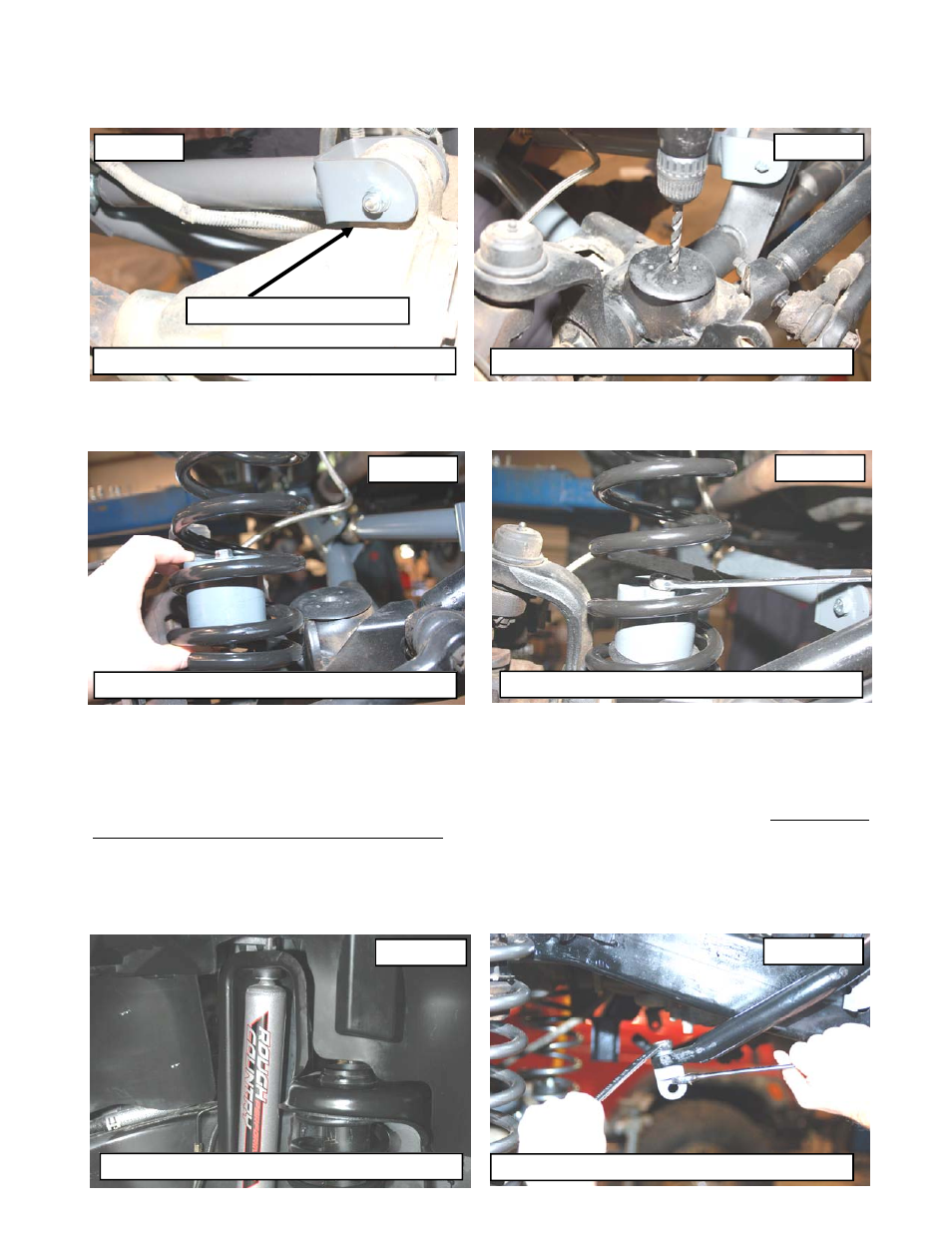
48.Locate the front shock absorber and install in the factory lower mounts with the factory hardware—The 2.2 series
shocks are designed to have piston mounted down. See Photo 26. Install the new upper stud bushings and
tighten the upper mounting point using a 9/16” wrench, slightly bulging the bushing. Do not over tighten stud bush-
ing. Tighten the bar pin on the bottom of the shock with the stock hardware using a 12mm wrench.
49.Install the upper sway bar mount on the top of front sway bar where the stock link was secured, using the supplied
3/8” x 1.25” bolt, lock washer, and washer. Tighten using a 9/16” wrench making sure the mount is straight. Note
that washer will conform to sway bar surface and be pulled in. See Photo 27.
PHOTO 24
PHOTO 22
Install upper arm to axle with 10mm x 80mm bolts
PHOTO 23
Drill the Fr lower mount using a 11/32” drill bit
Put spacer and bolt in coil
Cut out on driver side
PHOTO 25
Install self tapping bolt in drilled hole
PHOTO 26
2.2 Shock Absorber Shown
PHOTO 27
Install mounting pin on axle