Rough Country PERF663 User Manual
Page 9
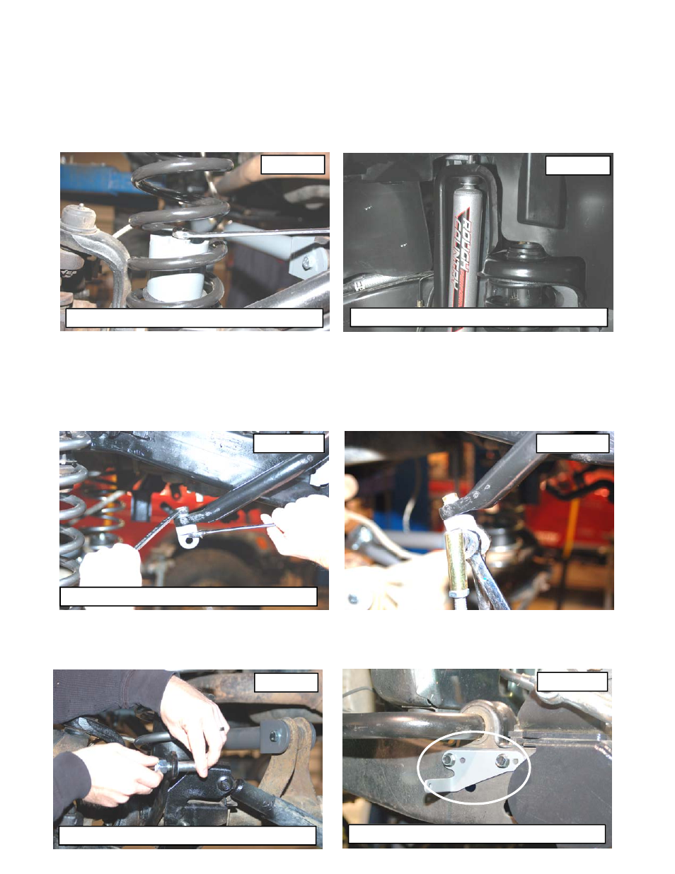
38.Tighten the bump stop extension bolt with a 9/16 wrench. Do not over torque the bolt. See Photo 22.
39.Remove the cotter pin and nut from the drag link at the pitman arm. Retain the nut to be reused. Separate the
drag link ball stud from the pitman arm with a puller tool. Do not use a pickle fork.
40.Mark the position of the original pitman arm. Remove the nut and washer from the steering gear box. Align and
install new pitman arm on the steering gear shaft. Install the washer and nut. Tighten to 185 ft. lbs.
41.Locate the front 2.2 Series shock absorber and install in the factory lower mounts with the factory hardware—
these shocks are designed to have piston mounted down. See Photo 23. Install the new upper stud bushings and
tighten the upper mounting point using a 9/16” wrench, slightly bulging the bushing. Do not over tighten stud bush-
ing. Tighten the bar pin on the bottom of the shock with the stock hardware using a 12mm wrench.
42.Install the upper sway bar mount on the top of front sway bar where the stock link was secured, using the supplied
3/8” x 1.25” bolt, lock washer, and washer. Tighten using a 9/16” wrench making sure the mount is straight. Note
that washer will conform to sway bar surface and be pulled in. See Photo 24.
43.Assemble the sway bar link with the link body, the jam nut and rod end Adjust the sway bar to a length of 11 1/4”
from top to bottom. Tighten the jam nut against the rod end using a 5/8” & 3/4”wrench.
44.Install the link on the upper sway bar mount with the supplied 1/2” flange lock nut as shown in Photo 25. Tighten
using a 5/8” & 3/4” wrench.
45.Install the supplied pin on the axle as shown in Photo 26. Tighten using a 3/4” wrench.
46.Remove the bolts securing the plastic shroud to the frame and install the driver and passenger side frame mount
brackets in the holes shown for the 4” disconnect kit using the factory holes and the supplied 1/4” x 3/4” bolts &
washers. See Photo 4. Tighten using a 7/16” wrench, be careful to not over tighten.
PHOTO 22
PHOTO 23
Install self tapping bolt in drilled hole
Install shock absorbers
PHOTO 24
Install mounting pin on axle
PHOTO 25
PHOTO 27
Install sway bar link frame bracket
PHOTO 26
Install mounting pin on axle