Th-2040-vtr installs pg1&2_revision_01-02 – Atdec Telehook TH-2040-VTR Installation manual User Manual
Page 2
No portion of this document or any artwork contained herein should be reproduced in any way without the express written consent of Atdec Pty Ltd.
Due to continuing product development, the manufacturer reserves the right to alter specifications without notice. Published: 23.11.11 ©
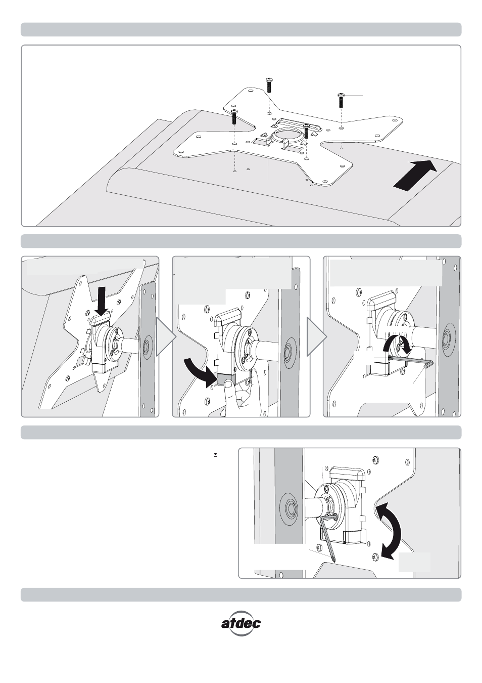
Step 4. Attach your Display to the Wall Mount Assembly
Step 5.
Adjust the VESA Ball Mount
Installation Complete
Combined Phillips-head
Screwdriver/Allen Key
supplied
Step 3. Attach the VESA plate to your Display
Position your Display to the desired viewing angle, using the 20°
angular movement allowed by the VESA Ball Mount.
Depending on the weight of the display, it may be necessary to make
adjustments to the VESA Ball Mount. If the display does not hold its
position, or is too resistant, adjust the Tension Plate located at the
rear of the VESA Ball Mount (see diagram right).
To make any adjustments tension evenly using the 3mm Allen Key
supplied. Apply half a turn at a time to each screw on the Tension
Plate to adjust evenly.
Check the display, and then adjust again if necessary.
Tension
Plate
Loosen
(-Kg)
Tighten
(+Kg)
(Optional) Insert the Security Screw
supplied and tighten using a
Phillips-head Screwdriver.
Press and hold the Release Buttons.
Gently insert bottom of VESA Plate
into Quickshift Mount. Release
Buttons to lock
in place.
Security
Screw
Combined Phillips-head
Screwdriver/Allen Key
supplied
Hook the top of the VESA Plate onto
the VESA Ball Mount.
Back of Display
There are three mounting hole configurations:
• 100mm x 100mm
• 200mm x 100mm
• 200mm x 200mm
Choose appropriate Mounting Screws
from the Hardware supplied to suit
your Display.
Back of Display
Top of
Display
Mounting Screws (x4)
VESA plate
TIGHTEN