Atdec Telehook TH-2040-VTR Installation manual User Manual
Th-2040-vtr
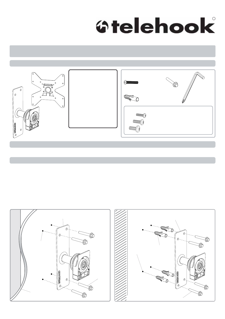
Component Checklist
Step 1. Component Checklist
Check you have received all parts against the Component Checklist above.
Hardware
Mounting Fasteners
Wall Mount
Assembly (x1)
Step 2. Installing the Wall Mount Assembly (choose from one of the following options)
For mounting Telehook to a Timber Stud Wall - Using the Wall Mount Assembly Bracket, mark
the location of the 4 holes and drill using a 4mm drill bit. Secure the bracket to the wall using the M6 Coach
Screws as shown in diagram A.
For mounting Telehook to a Masonry Wall - Using the Wall Mount Assembly Bracket, mark
the location of the 4 holes and drill using an 8mm masonry drill bit. Secure the bracket to the wall using the M6
Coach Screws and Nylon Anchors as shown in diagram B.
A. Timber Stud Wall
B. Masonry Wall
Note: This product will suit VESA compliant displays with 100x100mm, 200x100mm, and 200x200mm hole patterns only.
It will support up to a maximum weight of 25kg (55lbs).
TM
Flat Screen Wall Mount | Tilt
Installation Instructions
TH-2040-VTR
TOOLS REQUIRED:
• Power Drill
• Phillips-head Screwdriver
• 4mm (
3
/
16
”) Drill Bit
• 8mm (
5
/
16
”) Masonry Drill Bit
• 8mm (
5
/
16
”) Socket Wrench
or Shifter
Combined 3mm
Allen Key and
Phillips-head
Screwdriver (x1)
Hardware
(Optional)
Security
Screw (x1)
M6 Coach
Screws (x4)
Nylon
Anchor (x4)
VESA
plate (x1)
Wall Mount Assembly
Bracket
M6 Coach
Screw
4 x 4mm
Holes
Wall Material
Stud
Wall Mount Assembly
Bracket
M6 Coach Screw
4 x 8mm
Holes
Masonry Wall
Nylon Anchor
M4x16mm / M4x25mm Screw (x4 each)
M5x16mm / M5x25mm Screw (x4 each)
M6x16mm / M6x30mm Screw (x4 each)