Wheel bearing adjustment – Spicer Drive Axles Service Manual G & M User Manual
Page 25
23
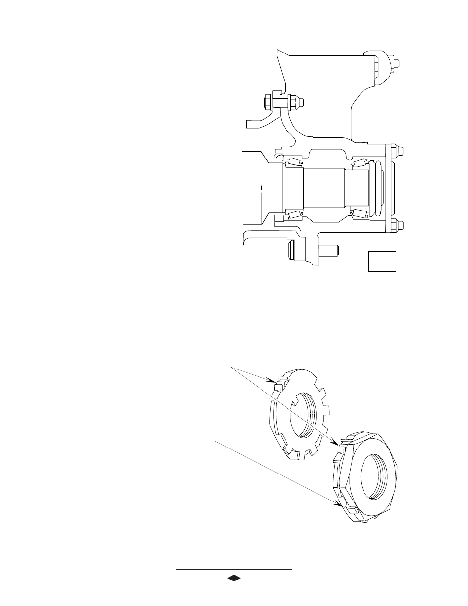
WHEEL BEARING ADJUSTMENT
,,,
,,
,
,,
,
,
,
LUBRICANT LEVEL
LUBRICANT LEVEL
LUBRICANT LEVEL
LUBRICANT LEVEL
LUBRICANT LEVEL
NOTE: Wheel bearings should be adjusted following
vehicle manufacturers recommended maintenance
schedule.
1. Block wheels not being adjusted to insure that
vehicle will not roll. Release emergency brake.
2. Raise wheel to be adjusted off of the ground. Make
certain wheel rotates freely.
3. Remove axle shaft.
4. Remove outer adjusting nut and lock if tabs are
broken.
5. Torque inner wheel nut to 50 Lb-Ft (68 N-m) while
rotating wheel one direction, then the other direc-
tion. Back off inner nut 1/4 turn.
NOTE: When replacing wheel bearings, new bearings
must be re-seated to insure maximum service reliability.
After the hub and bearings are assembled in place on
the spindile, install the inner adjusting nut. Tighten the
inner adjusting nut to 120 - 140 Lb-Ft (163-190 N-m),
while rotating the hub to seat the bearings. Back off the
adjusting nut 1/2 turn and follow the proedure outlined
in step #5.
6. Install lock against inner wheel nut, with locking
portion positioned on either the flat side of inner
nut or peak of inner nut, as shown.
7. Install outer wheel nut and torque to 250-275 Lb-Ft
(340-373 N-m). Rotate wheel in both directions.
Wheel must rotate freely, with out binding.
8. Bend one tang of lock over flat portion of outer
wheel to secure.
9. Remove old axle flange gasket and clean mating sur-
faces of hub and axle flange.
10. Install new axle flange gasket.
11. Install axle shaft. Torque axle nuts to vehicle
manufacturers specifications.
Wheel Bearing Adjustment Complete