Pinion assembly – Spicer Drive Axles Service Manual G & M User Manual
Page 16
8. Rotate carrier to a vertical position. Place pinion
bearing spacer (selective) on pinion. Install outer
bearing cone onto pinion.
NOTE: The reason for not assembling a new pinion oil
seal at this time is due to the possibility of having to
adjust pinion preload or pinion position. It would be
necessary to again remove the seal and, as mentioned,
whenever seals are removed, they are to be discarded
because of possible damage.
9. Inspect end yoke seal surface for grooves caused by
seal lip. If grooves can be detected with a fingernail,
yoke should be replaced or have repair sleeve
installed.
10. Assemble end yoke, washer and old flanged hex nut
onto pinion. Torque nut to 700-900 Lb-Ft (949-
1,220 N-m). The old nut can be used during this
adjustment phase of the assembly, saving the new
one for final assembly.
11. Remove pinion retainer strap. Using an in-lb torque
wrench rotate pinion noting rolling torque. Rolling
torque of pinion should read between 20-50 in-lb
(2.3-5.7 N-m).
To increase preload, decrease thickness of preload
spacer: to decrease preload, increase thickness of
preload spacer. Every .001" (.025 mm) change in
thickness of preload spacer changes torque to
rotate by approximately 30 in-lb.
NOTE: A pinion bearing spacer (selective) is used to
develop pinion bearing preload. See list in next column
for available thicknesses. Measure the spacer with a
micrometer before assembly to insure correct thickness.
12. Remove flanged hex nut, washer and end yoke.
Apply a light coat of lubricant to the lip of the seal
and assemble into housing.
13. Assemble end yoke, washer, and new flanged hex
nut. Torque to 700-900 Lb-Ft (949-1,220 N-m).
Recheck torque to rotate.
PINION ASSEMBLY
14
Pinion bearing spacers (selective) are available in the
following thicknesses.
Inches
MM
Inches
MM
.700
17.780
.714
18.136
.701
17.805
.715
18.161
.702
17.831
.716
18.186
.703
17.856
.717
18.212
.704
17.882
.718
18.237
.705
18.907
.719
18.263
.706
18.932
.720
18.288
.707
18.958
.721
18.313
.708
18.983
.722
18.339
.709
18.009
.723
18.364
.710
18.034
.724
18.390
.711
18.059
.725
18.415
.712
18.085
.726
18.440
.713
18.110
.727
18.466
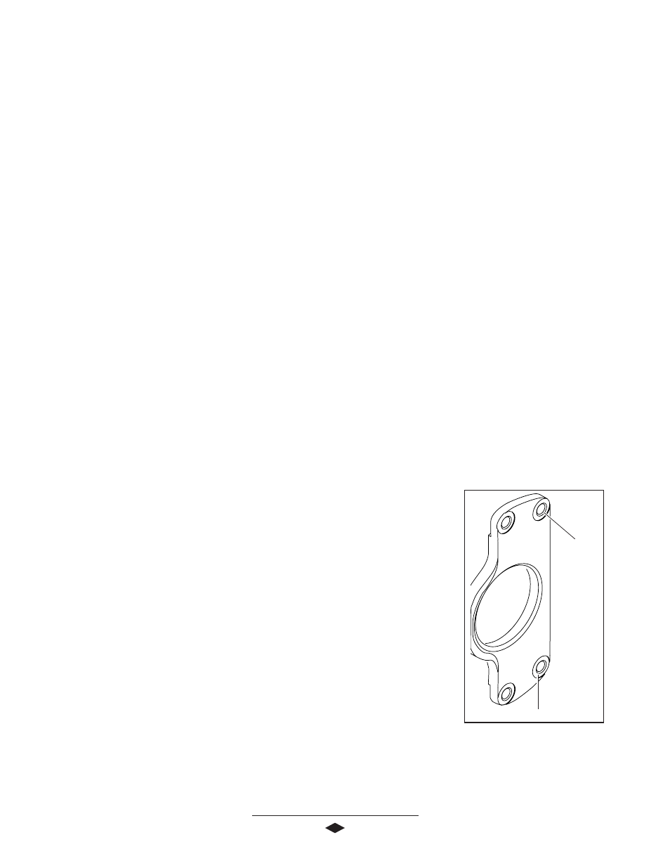
NOTE: Inspect pinion pilot bearing cap for proper
spotface and chamfer at the four bolt holes as shown in
Figure 10. If spotface and chamfer are not present,
machine as required .030 chamfer X 45º for holes and
1.25" spotface X .030
deep at four places.
14. Rotate carrier to
vertical position
with yoke down.
Install pinion pilot
bearing cap using
soft hammer if
necessary.
15. Install four retainer
bolts. Torque to:
G Model 70-80 Lb-
Ft (95-108 N-m)
M Model 110-125
Lb-Ft (149-169 N-m)
Chamfer
.030 x 45º
FFFFFigur
igur
igur
igur
igure 1
e 1
e 1
e 1
e 10
0
0
0
0
.030 Deep x 1.25 Spotface
Pinion Assembly Complete