Pinion disassembly – Spicer Drive Axles Service Manual User Manual
Page 11
9
1. Remove pinion bearing cage mounting bolts.
2. Remove pinion bearing cage and cage assembly from
carrier housing. If difficulty is encountered in
removing pinion assembly from carrier, place a brass
drift on inner end of pinion and tap lightly.
NOTE: Retain shims for possible use during
reassembly.
3. Mount pinion assembly in a soft jawed vise or
fixture, holding yoke or pinion stationary. Remove
roll pin, nut, and spacer.
4. Remove the end yoke or drive gear using a suitable
press.
5. Remove pinion from cage assembly.
6. Located between pinion bearings is a selective
spacer, used for pinion bearing preload. Retain this
spacer for possible use in reassembly.
7. Remove old pinion seal and discard. Always replace
it with a new seal at time of reassembly.
8. Lift out the outer pinion bearing cone.
9. Remove inner pinion bearing cup, using a suitable
adapter and press or puller.
10. Remove roller bearing from end of pinion.
11. Remove inner bearing cone from pinion.
Pinion Disassembly Complete
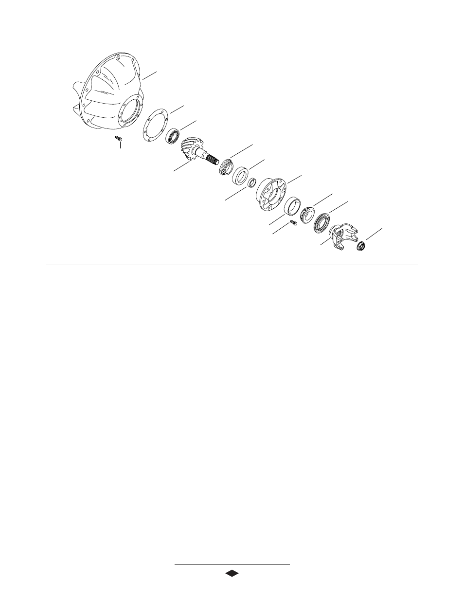
PINION DISASSEMBLY
Carrier Housing
Carrier Mounting Bolt
(100-120 Lb-Ft)
(136-162 N-m)
Inner Pinion Bearing Cup
Pinion Position Shim(s)
Outer Pinion Bearing Cone
Pinion Bearing Cage
Pinion Oil Seal
Flanged Hex Nut
(700-900 Lb-Ft)
(950-1,220 N-m)
End Yoke Assembly
Outer Pinion Bearing Cup
Inner Pinion
Bearing Cone
Pinion
Pinion Pilot Bearing
Pinion Bearing Cage Bolts
(160-180 Lb-Ft)
(217-244 N-m)
Bearing Preload Spacer