Ohaus VX SERIES FLOOR SCALES Indicator T32XW Manual en User Manual
Page 13
EN-
3000 Series Indicators
Remove the four hex head screws from the rear housng.
Open the housng by carefully pullng the top of the front housng forward.
Once all connectons are made, reattach the front housng.
The screws should be tghtened fully to mantan a watertght seal.
2.3.2 Scale Base to the Indicator
Pass the load cell cable through the stran relef (Fgure 1-1,
tem 10) and attach t to termnal block J5 (Fgure 1-2, tem 5).
Re-tghten the stran relef to ensure a watertght seal.
Pin
Connection
J5-1
+EXCITATION
J5-2
+SENSE
J5-3
+SIGNAL
J5-4
GND
J5-5
-SIGNAL
J5-6
-SENSE
J5-7
-EXCITATION
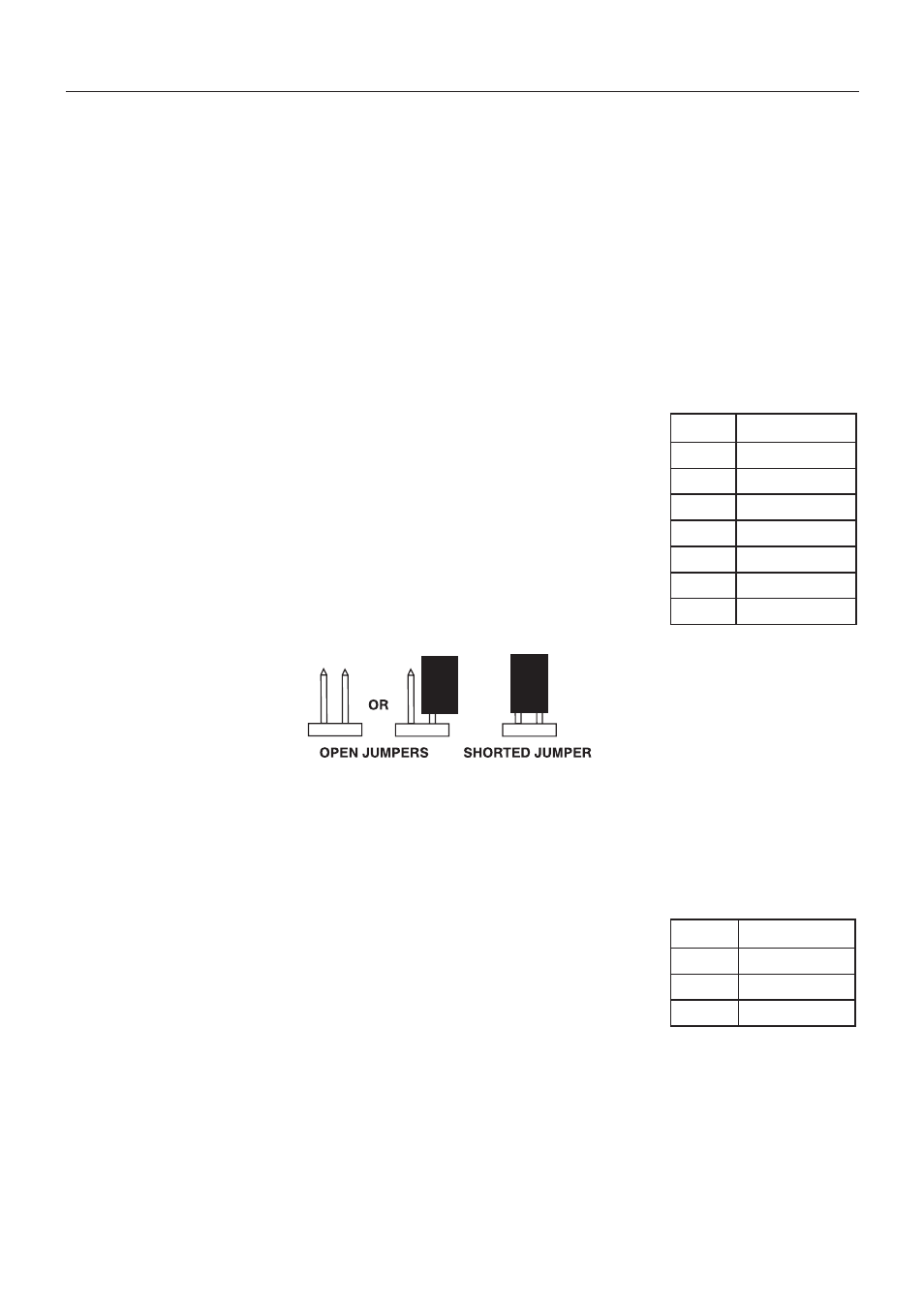
Jumper Connections
For a 4-wre load cell wth no sense wres: Jumpers W1 and W2 must be shorted.
For a 6-wre load cell that ncludes sense wres, see Fgure 2-2. Jumpers W1 and W2 must
be opened.
For load cells wth an extra ground sheld wre: Connect the sheld to the center poston (GND)
of J5.
After wrng s completed and jumpers are n place, replace the ndcator housng screws. Make sure the stran relef s properly
tghtened.
Fgure 2-2. Jumper Connectons.
2.3.3 RS232 Interface Cable to the indicator
Pass the optonal RS232 cable through the stran relef (Fgure 1-1, tem 9) and attach t to
termnal block J7 (Fgure 1-2, tem 7). Re-tghten the stran relef to ensure a water tght seal.
Pin
Connection
J7-1
TXD
J7-2
RXD
J7-3
GND