MSD 6214 Midget DIS-2 Programmable Race Ignition Installation User Manual
Page 7
INSTALLATION INSTRUCTIONS
7
M S D
• W W W . M S D P E R F O R M A N C E . C O M • ( 9 1 5 ) 8 5 7 - 5 2 0 0 • F A X ( 9 1 5 ) 8 5 7 - 3 3 4 4
Grounds: A poor ground connection can cause many frustrating problems. When a wire is
specified to go to ground, it should be connected to the
battery negative terminal, engine
block and chassis. There should always be a ground strap between the engine and chassis.
Always securely connect the ground wire to a clean, paint free metal surface.
Spark plug wire routing: The MSD Coil Pack has two channels. With the coil's wiring har-
ness facing you and looking from the top, the two terminals on the left are Channel 1 and the
two on the right are Channel 2. Channel 1 connects to the first and third cylinders in the firing
order. Channel two fires the second and fourth cylinders of the engine’s firing order. (Since
this is a waste spark system each channel of the coil fires its two cylinders at the same time.)
SETTING STATIC TIMING
By positioning the engine at your desired timing and lining up the trigger magnet and the
pickup, the timing will be close enough to start. Then your final adjustments can be set. Note
that a fully degreed hub is necessary for accurate timing settings.
Roll the engine over so cylinder #1 in the firing order is at the desired timing value then add
another 4°. This additional 4° is a computational lag associated with the magnetic pickups and
requires this compensation to achieve accurate timing throughout the entire rpm range. This
pickup should be connected to the Violet and Green wiring harness.
Next roll the engine over so the second cylinder in the firing order is at the desired timing
value (as used for the first cylinder). Line up the second pickup (Light Blue and Light Green
wires) with the magnet.
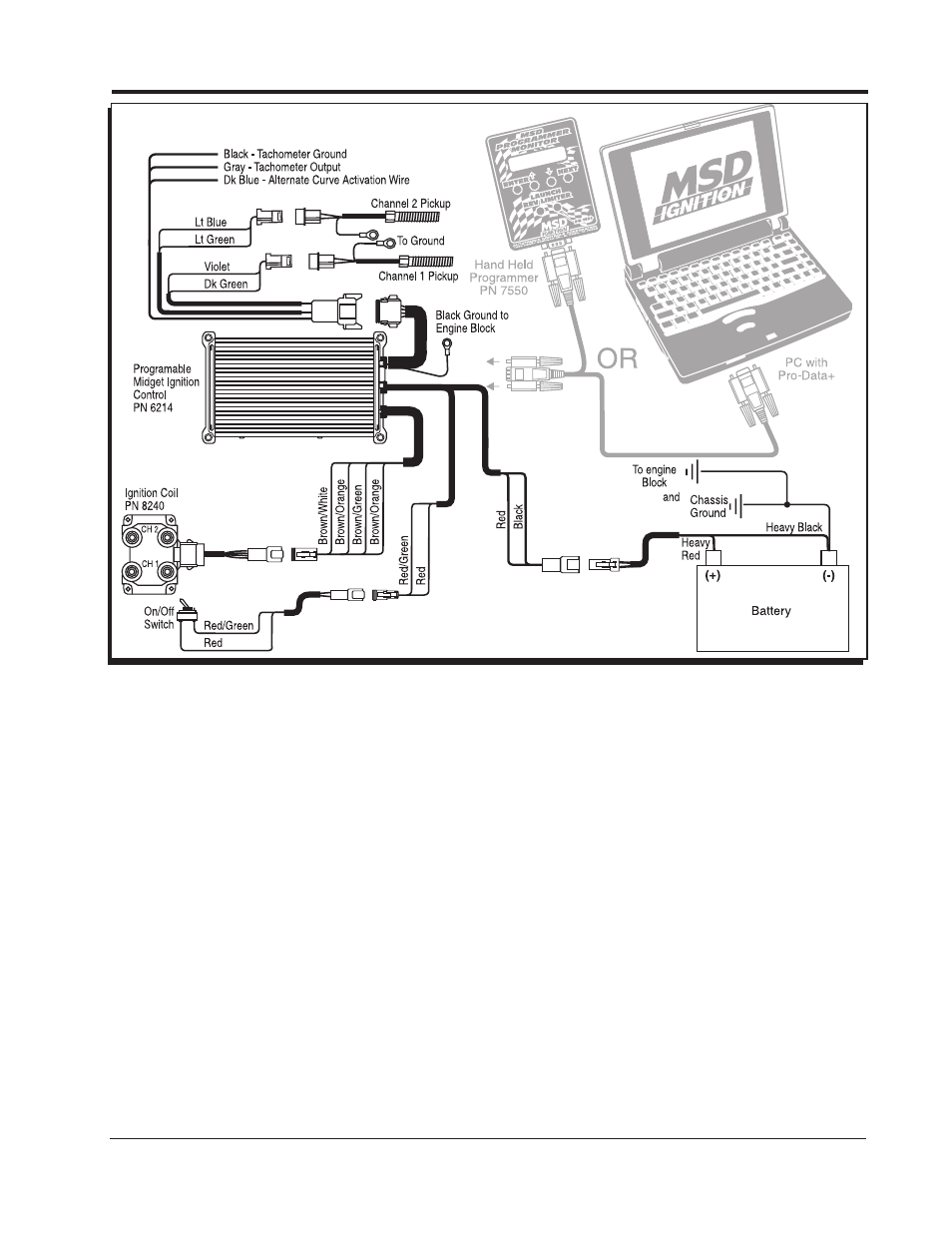
Figure 5 Wiring the MSD Programmable Midget Ignition System.